
 WhatsApp: +86 16626708626
 Email:
  Phone: +86 16626708626
Description
Key Technical Specifications
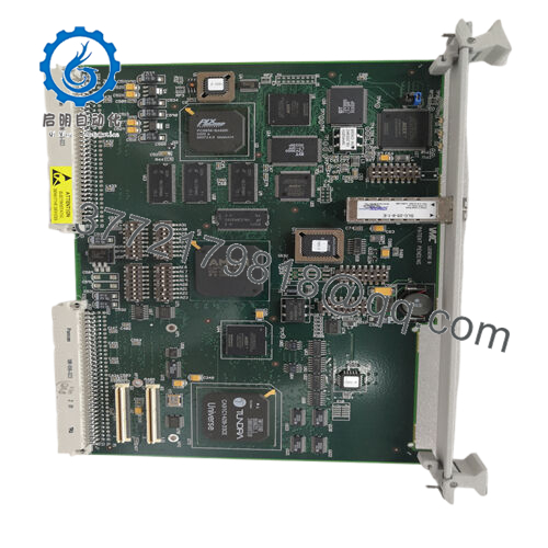
- Function: Master module for VMEbus fiber-optic repeater link
- Data Transfer Rate: Up to 1 MB/s
- Addressing Modes: 16-bit, 24-bit, 32-bit
- Data Transfer Types: 8-bit, 16-bit, 32-bit bidirectional
- Link Medium: Fiber-optic cable (supports distances from 5 ft to over 6,500 ft depending on configuration)
- Isolation: Complete electrical isolation between linked VMEbus systems
- System Controller: Capable of providing system controller functions in slave chassis
- Operating Temperature: 0 to 55°C (typical for VMIVME series; verify exact revision)
- Power Requirements: Standard VMEbus +5V backplane power (exact draw depends on configuration)
- Form Factor: 6U VMEbus single-slot module
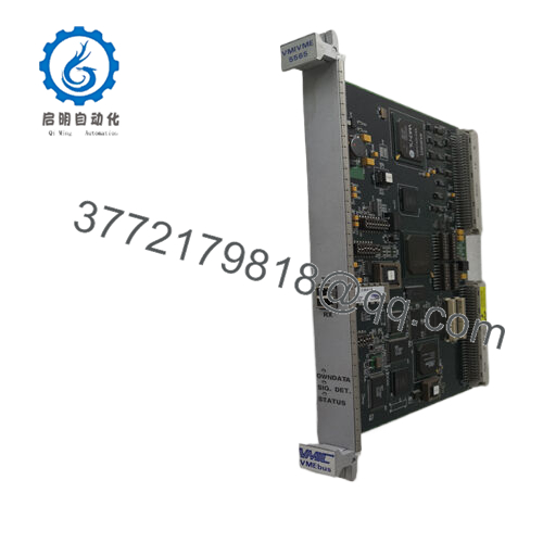
- Status Indication: Dual-color LED for link status (green = good link)
- Additional Features: Plug-and-play operation, burst mode support, link reset capability
The VMIVME-5532M serves as the master module in the VMIVME-5532 VMEbus fiber-optic repeater link set. It connects multiple VMEbus chassis together over fiber-optic cable, allowing a single master CPU to control I/O boards located in remote slave chassis. This setup sees common use in distributed control systems, test equipment, and military/aerospace applications where electrical isolation and noise immunity matter.
In field deployments of older VMEbus systems, this module provides reliable extension without software overhead. It maintains full transparency for bus operations while delivering total galvanic isolation that eliminates ground loops and reduces EMI issues. Engineers often choose it over copper-based extenders when long distances or harsh electrical environments exist. Always cross-check the exact revision and paired slave module (typically VMIVME-5532S) against your system documentation before installation.

- VMIVME-5532M
Installation & Configuration Guide
Stage 1: Pre-Installation Preparation (10-15 minutes) ⚠️ Safety First: Notify operations of scheduled downtime. Verify the system reaches a safe state. Perform lockout/tagout on the VMEbus rack power. Wait at least 5 minutes for capacitors to discharge. Tools Required: Grounded ESD wrist strap, Phillips screwdriver, digital multimeter, wire labels, smartphone for documentation photos. Data Backup: Export any relevant configuration files. Photograph the existing module’s front panel, LED status, and any jumper or switch settings. Document fiber-optic cable routing and connections.
Stage 2: Removing the Old Module (5 minutes)
- Remove the front panel bezel or cover if present.
- Label and carefully disconnect the fiber-optic cables (do not bend sharply or force connectors).
- Release the VMEbus board ejectors or locking tabs. Pull the module straight out to avoid damaging backplane pins.
- Inspect the backplane slot for bent pins, dust, or corrosion.
⚠️ Note: Keep the old module on hand for direct comparison until the new unit operates without faults.
Stage 3: Installing the New Module (10 minutes)
- Put on the ESD wrist strap and connect it to a grounded point. Verify the replacement carries the exact VMIVME-5532M designation.
- Configuration Clone (Crucial): Match any jumpers or settings from the old module photo. Most units ship with factory defaults for plug-and-play.
- Align the board with the slot guides and insert firmly into the VMEbus rack until it seats fully (listen for the mechanical click). Secure the front panel screws or ejectors.
- Reconnect the fiber-optic cables to the corresponding TX/RX ports. Use proper torque on any retaining hardware.
Self-Checklist: [ ] Module seated and locked, [ ] Fiber cables secure and clean, [ ] ESD precautions followed.
Stage 4: Power-On & Testing (10-15 minutes) Pre-Power Check: Use a multimeter to verify no shorts on the +5V rail to ground. Power-On Steps:
- Apply power to the VMEbus rack only (keep field devices isolated if possible).
- Observe the dual-color LED: Green indicates a good link; check the paired slave module for matching status.
- Verify bus arbitration and system controller functions if the module provides them.
- Run a simple read/write test across the link to confirm transparent operation.
- Monitor for stable operation over at least 30 minutes under load.
⚠️ Troubleshooting Note: Solid red or no LED usually points to fiber connection issues or mismatched master/slave pairing. No bus access may indicate improper slot placement or backplane problems. If the link fails to establish, clean fiber ends and re-seat cables first.
Frequently Asked Questions (FAQ)
Can this module be hot-swapped under power? No. The VMIVME-5532M is not designed for hot-swapping. Removing or inserting it under power risks damaging the VMEbus backplane or the module itself. Always shut down the affected chassis power first.
Is the VMIVME-5532M obsolete, and is the unit genuinely new? This series dates back to the VMIC/GE Fanuc era and is now considered obsolete by current manufacturers. Units offered as New Surplus come from unused original stock with full traceability where possible. We perform inbound verification plus functional testing on a VMEbus rack before shipment.
What pairs with the VMIVME-5532M as the slave side? Use the matching VMIVME-5532S slave module in the remote chassis. The master (M) and slave (S) pair together to create the transparent link. Mixing revisions can cause compatibility problems.
Will I lose programming or configuration when replacing this module? No. The VMIVME-5532M functions as a transparent bus repeater and does not store application logic. Your existing CPU programming and I/O configurations remain unaffected as long as the link re-establishes correctly.
Why is the price lower than current OEM list pricing? These units come from new surplus inventory rather than active factory production. We test every board functionally, but buyers must still verify final compatibility with their specific VMEbus system and firmware.
How far can the fiber-optic link extend? Distance depends on fiber type and quality. The design supports spans from a few feet up to several thousand feet. Consult the original datasheet for attenuation limits and recommended cable specifications.
Keep these checks in mind and you will avoid most common replacement issues. Test videos and detailed photos of the specific unit are available upon request. Verify precise compatibility with your system documentation before final installation.


