
 WhatsApp: +86 16626708626
 Email:
  Phone: +86 16626708626
Description
3. Key Technical Specifications
| Parameter | Value |
|---|---|
| Model Number | VMIVME-5550 |
| Manufacturer | GE Fanuc / VMIC |
| Product Type | Reflective Memory Interface Module |
| Bus Interface | VME64x |
| Network Technology | Reflective Memory |
| Fiber Optic Speed | 2.12 Gbaud |
| Reflective Memory Size | 256 MB SDRAM |
| Memory Access Mode | Shared Deterministic Memory |
| Fiber Ports | Dual LC Fiber Connections |
| Network Topology | Ring Network |
| Data Replication | Hardware-Based Automatic Replication |
| DMA Support | Yes |
| Interrupt Support | Yes |
| VME Addressing | A16, A24, A32 |
| Data Width | D16, D32, D64 |
| Error Detection | Built-In Network Diagnostics |
| Latency | Deterministic Real-Time Transfer |
| Operating Temperature | 0 °C to +55 °C |
| Form Factor | 6U VME64x Module |
| Product Status | Discontinued by OEM |
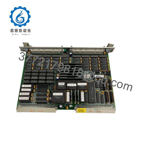
The VMIVME-5550 is a high-speed reflective memory interface module designed to provide deterministic data sharing across distributed real-time systems using a fiber-optic network. Memory writes performed on one node are automatically replicated to every node in the network without software intervention.
4. Product Introduction
The GE VMIC VMIVME-5550 is a VME64x reflective memory module used in real-time control systems where multiple processors must share data with predictable latency. Typical applications include turbine control simulators, aerospace test facilities, power generation systems, military training simulators, and large-scale hardware-in-the-loop (HIL) platforms.
In field deployments, the VMIVME-5550 was often selected because it eliminates the timing uncertainty associated with Ethernet-based communications. Any processor writing data into reflective memory automatically updates all connected nodes through dedicated fiber-optic hardware, making synchronization straightforward for deterministic control applications.

- VMIVME-5550
- VMIVME-5550
5. Installation & Configuration Guide
Stage 1: Pre-Installation Preparation (10 Minutes)
⚠️ Safety First
- Notify operations personnel of planned downtime.
- Verify all controlled systems are in a safe state.
- Apply Lockout/Tagout (LOTO).
- Remove power from the VME chassis.
- Wait at least 5 minutes for power supply discharge.
Tools Required
- ESD wrist strap
- PH1 screwdriver
- Fluke 115 multimeter
- Fiber cleaning kit
- Cable labels
- Smartphone camera
Data Backup
- Export reflective memory configuration files.
- Record node IDs.
- Record memory map assignments.
- Photograph jumper and switch settings.
- Document fiber routing.
- Record interrupt configuration parameters.
Stage 2: Removing the Old Module (5 Minutes)
Steps
- Disconnect fiber-optic cables.
- Label TX and RX fibers.
- Remove front-panel screws.
- Release extraction handles.
- Pull the module straight out.
⚠️ Note
Do not immediately discard the original module. Keep it available until network integrity and memory synchronization are verified.
Inspection Checklist
- No bent VME connectors
- No fiber contamination
- No damaged LC connectors
- No backplane damage
Stage 3: Installing the New Module (10 Minutes)
Steps
- Attach ESD protection before handling the board.
- Verify exact model number:
- VMIVME-5550
- Configuration Clone (Critical)
- Match node configuration.
- Match interrupt settings.
- Match memory map assignments.
- Insert board into card guides.
- Seat fully into VME backplane.
- Tighten retaining screws.
- Reconnect fiber cables.
- Clean fiber ends before connection.
Self-Checklist
- Model verified
- Fiber connections correct
- Configuration matched
- Board seated fully
- Connectors secured
Stage 4: Power-On & Testing (20 Minutes)
Pre-Power Check
- Verify VME power rails.
- Verify fiber cleanliness.
- Check grounding.
Power-On Steps
- Energize the VME rack.
- Verify module startup indicators.
- Check fiber link status LEDs.
- Verify network ring integrity.
- Confirm memory replication.
- Test interrupt generation.
- Validate DMA operation.
- Verify application synchronization.
⚠️ Troubleshooting Note
- Link fault LEDs: Check fiber polarity and cleanliness.
- Missing memory updates: Verify node addressing.
- Intermittent communication: Inspect ring topology continuity.
- Synchronization errors: Verify memory map consistency.
SOP Quality Transparency
1. Inbound Inspection & Traceability
Every VMIVME-5550 undergoes:
- OEM label verification
- Serial number recording
- Anti-counterfeit inspection
- Visual inspection for:
- Connector wear
- PCB damage
- Corrosion
- Rework marks
- Documentation review when available
2. Live Functional Testing
Testing is performed on a genuine reflective memory test network.
Procedures include:
- Power-on self-test
- Fiber link verification
- Memory replication testing
- Interrupt testing
- DMA transfer validation
- Multi-node synchronization testing
- Continuous operation exceeding 24 hours
- Thermal monitoring
An official test report is available upon request.
3. Electrical Parameter Testing
- 500 V insulation resistance test (>10 MΩ)
- Ground continuity verification
- Power consumption verification
- Fiber transceiver diagnostics
4. Firmware & Configuration Verification
- Firmware revision documented
- Hardware revision recorded
- Node configuration archived
- Switch and jumper settings photographed
5. Final QC & Packaging
- QC inspector sign-off
- Anti-static ESD packaging
- Fiber connector protection caps installed
- Shock-resistant export carton
- QC Passed label with inspection date
Test videos and operational photos are available upon request.
Technical Pitfall & Survival Guide
❗ Firmware Revision Mismatch
I’ve seen a reflective memory network operate flawlessly for years until a replacement board with a different firmware revision was introduced.
The board powered up normally. Memory replication did not.
The resulting troubleshooting effort consumed nearly two days.
Avoidance:
- Document firmware revisions before removal.
- Verify compatibility across all nodes.
- Request matching firmware whenever possible.
❗ DIP Switch / Jumper Misconfiguration
This is the most common rookie mistake, but experienced engineers make it too.
Take a picture before you pull it. I can’t stress this enough.
Avoidance:
- Photograph every switch bank.
- Record node IDs.
- Record interrupt settings.
- Verify memory map assignments.
❗ Terminal Block / Fiber Connection Errors
Reflective memory networks depend on proper ring continuity.
I’ve watched engineers accidentally reverse TX and RX connections and spend hours investigating software that wasn’t broken.
Avoidance:
- Label every fiber.
- Verify ring topology.
- Clean fiber connectors before installation.
❗ Power Draw Specifications
Many legacy VME systems operate close to power supply limits.
Adding replacement hardware without verifying rack loading can introduce random resets and communication faults.
Avoidance:
- Calculate rack power consumption.
- Maintain at least a 20% reserve.
- Verify cooling airflow.
❗ Electrostatic Discharge (ESD)
I once watched a technician unpack a reflective memory board directly onto a painted steel cabinet.
The board survived installation but developed intermittent fiber-interface faults shortly afterward.
That’s an expensive lesson.
Avoidance:
- Wear a grounded wrist strap.
- Use ESD-safe work surfaces.
- Keep modules in anti-static packaging until installation.
Keep these checks in mind and you’ll save yourself 90% of typical rework time.
6. Frequently Asked Questions (FAQ)
Q1. What does a reflective memory module actually do?
A reflective memory module creates a shared memory space across multiple systems.
When one processor writes data into reflective memory, dedicated hardware immediately replicates that data to every node on the fiber network. No polling or protocol stack is required.
This architecture is widely used in real-time simulation and deterministic control systems.
Q2. Can the VMIVME-5550 replace an older VMIVME-5576 or VMIVME-5588?
Not automatically.
While these products belong to the same reflective memory family, memory size, firmware revisions, network speeds, and driver requirements may differ.
Verify compatibility before ordering.
Q3. Is the VMIVME-5550 obsolete?
Yes.
The VMIVME-5550 belongs to a legacy GE Fanuc VMIC product family. OEM production has ended, and available inventory typically comes from surplus stock, strategic spares inventories, or tested industrial inventory.
Q4. Can I hot-swap this module?
No.
The VMIVME-5550 is not designed for hot insertion into a powered VME backplane.
Doing so can damage the module, disrupt the reflective memory ring, or cause backplane faults.
Always remove power first.
Q5. Will replacing the module affect my application software?
Potentially.
Most applications depend on specific driver versions, memory maps, interrupt settings, and firmware revisions.
Document the existing configuration before replacement.
Q6. Why is firmware matching important?
I’ve personally seen systems report healthy fiber links while refusing to synchronize memory.
The cause was a firmware revision difference between network nodes.
Always verify firmware compatibility before installation.
Q7. What condition is typically available?
Current inventory is generally offered as:
- New Original (New Surplus)
- Factory-Sealed Surplus
- Refurbished (Tested)
- Removed Working Spare


