
 WhatsApp: +86 16626708626
 Email:
  Phone: +86 16626708626
Description
Key Technical Specifications
| Parameter | Specification Value |
| Network Architecture | Reflective Memory (deterministic token ring / multi-drop) |
| Data Transfer Rate | Up to 174 MB/s (burst mode) over fiber optic links |
| Connection Media | Fiber optic transceiver interface (LC or ST connector variants) |
| Form Factor | 6U Single-Slot VMEbus |
| Onboard Memory | Shared high-speed dual-ported SRAM buffer |
| Maximum Node Count | Supports up to 256 interconnected nodes in a single ring |
| Network Dynamic Range | Distance up to 300 meters between nodes (multimode fiber) |
| Addressing Support | A24 or A32 memory mapping configurations |
| Current Consumption | +5 VDC (approx. 3.0 A maximum draw across the backplane) |
| Diagnostic Support | Real-time network link status and internal data error monitoring LEDs |
Product Introduction & Supply Chain Strategy
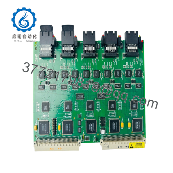
The GE VMIC VMIVME-5594 332-005594-001B is a specialized, hardware-driven Reflective Memory network interface module built on a 6U VMEbus architecture. Unlike standard Ethernet or fieldbus systems that rely on complex software protocol stacks, software routing, and packet decoding, this module replicates data at the hardware layer using ultra-low latency fiber optic connections. The moment a master processor writes data to its local VMIVME-5594 dual-port SRAM, the onboard transceiver automatically broadcasts that exact data payload to the memory spaces of all other node boards in the ring. This architecture makes it essential for highly coordinated systems like complex flight simulators, industrial engine testing banks, and multi-node defense telemetry arrays.
Because the system relies on physical, ring-wide hardware synchronization, an unexpected failure on a single VMIVME-5594 board will instantly break the fiber loop, causing data dropouts and triggering an emergency shutdown of the entire facility cluster. Since this series is completely obsolete, sourcing this exact “001B” assembly layout as a certified New Surplus part is a critical operational priority. Refurbished fiber optic modules run significant risks of laser diode degradation and optical attenuation anomalies, which can manifest as intermittent network dropouts. Securing a pristine, unissued New Surplus unit for your physical buffer stock guarantees proper transmission metrics and ensures complete protection against multi-day stock-out scenarios.

- VMIVME-5594 332-005594-001B
- VMIVME-5594 332-005594-001B
Installation & Configuration Guide
Stage 1: Pre-Installation (Prep & Safety)
- Safely de-energize the host VMEbus card cage. Implement comprehensive lock-out/tag-out (LOTO) field safety procedures.
- Fasten a grounded static-dissipative ESD wrist strap tightly to an unpainted, structural steel section of the cabinet.
- Review the layout of the surface jumpers and DIP switches on the existing board to document the node ID and memory address offset parameters.
- Set the switches and jumpers on the incoming New Surplus VMIVME-5594 module to replicate the original card configurations exactly.
Stage 2: Removal
- Loosen the upper and lower captive retention screws locking the front panel handles into place.
- Carefully disconnect the optical transmit (TX) and receive (RX) fiber lines from the front faceplate. Put protective dust caps on the open fiber terminations immediately.
- Pull the top and bottom injector/ejector handles outward simultaneously to free the board from the backplane J1/J2 tracks.
- Extract the card smoothly along the track channels and place it inside an ESD-shielded bag.
Stage 3: Installation (Clone & Seat)
- Clean out the VME slot backplane connectors with clean, dry compressed air if dust has accumulated.
- Align the board edges with the top and bottom plastic guide channels inside the chassis.
- Guide the card inward until the mechanical levers meet the frame, then pivot both levers inward with steady force to anchor the pins into the backplane blocks.
- Fasten the captive retaining screws on the front panel to secure structural grounding.
Stage 4: Power-On & Testing
- Remove the dust covers and insert the TX/RX fiber connections back into the front panel optical ports. Ensure correct alignment of the fiber loop.
- Clear the LOTO safety tags and power up the VME chassis.
- Monitor the front plate diagnostic LEDs. The network link state light must illuminate solidly, indicating a complete optical loop connection with the next node in the ring.
- Run your system’s software diagnostic routines to verify error-free, real-time memory writes across the shared memory network.
Firmware/Software Versions & Upgrade Notes
The VMIVME-5594 332-005594-001B operates as a direct memory-mapped node within standard VMEbus A24 or A32 memory allocations. Hardware tracking parameters and protocol execution logic are entirely hard-coded into the onboard field-programmable gate array (FPGA) logic blocks.
⚠️ CRITICAL INTEGRATION WARNING: The “001B” suffix indicates a specific generation of fiber transceivers and internal gate timings.
Mixing different hardware revisions (such as a 332-005594-001B mixed with an older non-B layout) can trigger minor variations in network token propagation delays. In highly sensitive systems running microsecond-level synchronization loops, this minor mismatch can trigger token timeout faults or unexpected interrupt errors. Always match the hardware assembly configuration suffix across all connected nodes in your network ring to ensure long-term timing stability.
Frequently Asked Questions (FAQ)
What makes Reflective Memory better than a standard high-speed network for real-time control?
Standard network protocols introduce unpredictability because they rely on software layers, collision handling, and packet processing overhead. Reflective Memory functions entirely at the hardware level. When a CPU writes data to the VMIVME-5594 module, that data is automatically replicated across the internal RAM of all other boards in the ring via fiber optics within microseconds. This process requires zero CPU overhead from the host operating system, ensuring perfect determinism.
Can I insert or extract this Reflective Memory module while the VME backplane is powered?
No. The legacy VMEbus specification utilized across the VMIVME-5594 family lacks hot-swap electrical shielding. Attempting a live insertion or extraction can create transient voltage arcs across the shared backplane data paths. This can permanently damage the onboard VME logic chips and cause adjacent processing modules in the chassis to fault out.
What happens to the network ring if one VMIVME-5594 node loses power?
If a node board in the ring completely loses power, its internal fiber optic transceiver can no longer regenerate the incoming optical signal, which breaks the token loop. To prevent a single-point failure from taking down your entire control infrastructure, we recommend implementing external, powered fiber optic bypass switches to maintain loop continuity if an individual chassis needs to be powered down for service.
How do I configure the distinct Node ID on this card?
The specific node ID (ranging from 0 up to 255) is configured using a dedicated block of physical DIP switches located directly on the PCB surface. Every individual Reflective Memory module installed in your fiber optic loop must be assigned a unique node address to prevent data collision errors across the shared network space.
Why choose a New Surplus VMIVME-5594 over a refurbished module?
Reflective Memory systems rely heavily on the integrity of high-speed fiber optic transceivers. Refurbished cards often come from high-temperature industrial environments where the laser diodes have suffered thermal aging, which leads to lower light output and intermittent data transmission errors. Our New Surplus inventory provides pristine, unused optical components with original factory calibration, delivering full operational longevity and preventing unexpected communication failures.


