
 WhatsApp: +86 16626708626
 Email:
  Phone: +86 16626708626
Description
3. Key Technical Specifications
| Parameter | Value |
|---|---|
| Model Number | VMIVME3114 (332-013114-000C) |
| Manufacturer | GE Fanuc / VMIC |
| Product Type | Analog Input/Output Board |
| Bus Interface | VMEbus |
| Analog Inputs | 8 Sample-and-Hold Input Channels |
| ADC Resolution | 12-bit |
| Analog Outputs | 2 Independent Analog Outputs |
| DAC Resolution | 12-bit |
| Input Voltage Ranges | 0 to +10 V, ±5 V, ±10 V |
| Output Voltage Ranges | 0 to +10 V, ±5 V, ±10 V |
| Programmable Gain | x1, x2, x4, x8, x16 |
| Maximum Input Scan Rate | 125 kHz (Gain = x1) |
| Maximum Output Update Rate | 125 kHz |
| Input Buffer Memory | Dual 128 KB Buffers |
| Output Buffer Memory | Dual 128 KB Buffers |
| Digital I/O | Dual 8-bit TTL Ports |
| Synchronization | Multi-board and external synchronization support |
| VME Addressing | A32/A24/A16 |
| VME Data Modes | D16, D08(EO), BLT D16 |
| Product Status | Discontinued by OEM |
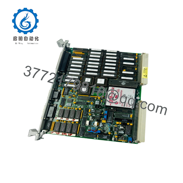
The VMIVME-3114 is a combined analog input/output board providing 8 sample-and-hold analog inputs, dual 12-bit analog outputs, programmable gain amplification, dual-port memory buffers, and dual 8-bit TTL I/O ports for VMEbus-based industrial and test applications.
4. Product Introduction
The GE VMIVME3114 (332-013114-000C) is a VMEbus analog input/output board designed for real-time data acquisition, process simulation, instrumentation, aerospace test systems, and industrial control applications. The board combines analog measurement and analog signal generation on a single VME module, reducing rack space requirements in legacy systems.
A notable characteristic of the VMIVME3114 is its integrated sample-and-hold architecture, programmable gain amplifier, dual-port memory buffering, and independent analog outputs capable of 125 kHz updates. In field support environments, these boards were often installed in turbine test stands, environmental simulation systems, and manufacturing process control platforms where both signal acquisition and signal generation were required simultaneously.

- VMIVME3114 332-013114-000C
- VMIVME3114 332-013114-000C
5. Installation & Configuration Guide
Stage 1: Pre-Installation Preparation (10 Minutes)
⚠️ Safety First
- Notify operations of planned downtime.
- Verify all connected equipment is in a safe state.
- Apply Lockout/Tagout (LOTO).
- Remove power from the VME chassis.
- Wait at least 5 minutes for capacitor discharge.
Tools Required
- ESD wrist strap
- PH1 screwdriver
- Fluke 115 multimeter
- Wire labels
- Smartphone camera
- VME rack documentation
Data Backup
- Export application configuration.
- Record VME slot assignment.
- Document analog scaling parameters.
- Photograph jumper settings.
- Photograph cable connections.
- Record trigger and synchronization settings.
Stage 2: Removing the Old Module (5 Minutes)
Steps
- Remove front-panel retaining screws.
- Label all field wiring and cables.
- Disconnect I/O cables carefully.
- Release extraction levers.
- Pull the board straight out to avoid backplane damage.
⚠️ Note
Keep the old module available until the replacement passes complete functional testing.
Inspection Checklist
- No bent VME pins
- No connector damage
- No contamination
- No corrosion
- No damaged card guides
Stage 3: Installing the New Module (10 Minutes)
Steps
- Wear ESD protection before handling the board.
- Verify exact model number:
- VMIVME3114
- 332-013114-000C
- Configuration Clone (Critical)
- Duplicate jumper settings exactly.
- Verify gain selections.
- Verify addressing configuration.
- Verify synchronization settings.
- Insert the board into card guides.
- Seat fully into the VME backplane.
- Tighten retaining screws.
- Reconnect all field cables.
Self-Checklist
- Model verified
- Jumpers matched
- Wiring secured
- Board seated correctly
- Retaining hardware tightened
Stage 4: Power-On & Testing (15 Minutes)
Pre-Power Check
- Verify +5 VDC supply voltage.
- Check for shorts using a multimeter.
- Confirm chassis grounding.
Power-On Steps
- Energize the VME rack.
- Verify board initialization.
- Confirm VMEbus communication.
- Test analog input channels.
- Verify programmable gain operation.
- Test both analog outputs.
- Confirm TTL I/O functionality if used.
- Validate synchronization and trigger functions.
⚠️ Troubleshooting Note
- No communication: Verify VME addressing.
- Incorrect analog values: Verify gain settings.
- Output signal errors: Check DAC configuration.
- Intermittent operation: Inspect backplane connector engagement.
SOP Quality Transparency
1. Inbound Inspection & Traceability
Every VMIVME3114 (332-013114-000C) undergoes:
- OEM label verification
- Serial number recording
- Anti-counterfeit inspection
- Visual inspection for:
- Corrosion
- PCB discoloration
- Rework marks
- Connector damage
- Documentation verification where available
2. Live Functional Testing
Testing is performed using a genuine VMEbus test chassis.
Procedures include:
- Power-on verification
- Analog input simulation
- Analog output generation verification
- Gain switching verification
- TTL I/O testing
- VMEbus communication testing
- Continuous operation exceeding 24 hours
- Thermal monitoring during operation
An official test report is generated upon request.
3. Electrical Parameter Testing
- 500 V Megger insulation resistance test (>10 MΩ)
- Ground continuity verification
- Backplane current measurement
- Analog channel validation
4. Firmware & Configuration Verification
- Hardware revision documented
- Jumper settings photographed
- Addressing configuration recorded
- Functional configuration archived
5. Final QC & Packaging
- QC inspector sign-off
- Anti-static ESD packaging
- Bubble-wrap protection
- Heavy-duty export carton
- QC Passed label with inspection date
Test photos and videos are available upon request.
Technical Pitfall & Survival Guide
❗ Firmware Revision Mismatch
While the VMIVME3114 relies heavily on hardware configuration, I’ve seen replacement boards create unexpected software issues because driver packages expected a different board revision.
The hardware looked identical. The software disagreed.
Avoidance:
- Record existing board revision.
- Verify driver compatibility.
- Match hardware revision whenever possible.
❗ DIP Switch / Jumper Misconfiguration
This is the most common startup problem on legacy VMIC hardware.
Take a picture before you pull it. I can’t stress this enough.
Avoidance:
- Photograph every jumper.
- Record gain settings.
- Record address settings.
- Verify synchronization selections.
❗ Terminal Block / Wiring Incompatibility
Even when connectors appear identical, field wiring assignments can vary between installations.
I’ve seen technicians reconnect everything based on memory and spend half a shift troubleshooting.
Avoidance:
- Label every cable.
- Verify wiring diagrams.
- Check analog signal references and grounds.
❗ Power Draw Specifications
Many VME racks have been running continuously for decades.
A power supply operating near capacity may tolerate the old board but become unstable after replacement.
Avoidance:
- Calculate rack power consumption.
- Maintain a 20% power margin.
- Verify cooling airflow.
❗ Electrostatic Discharge (ESD)
I once watched an engineer replace a VMIC analog board without a wrist strap during a winter outage.
The board passed initial startup and failed intermittently three days later.
Avoidance:
- Wear a grounded wrist strap.
- Use ESD mats.
- Keep boards in anti-static packaging until installation.
Keep these checks in mind and you’ll save yourself 90% of typical rework time.
6. Frequently Asked Questions (FAQ)
Q1. Can I hot-swap the VMIVME3114?
No.
The original VMIC documentation explicitly warns against installing or removing the board while power is applied to the VME system. Doing so risks damage to the board and backplane.
Q2. Is the VMIVME3114 obsolete?
Yes.
The VMIVME3114 belongs to the legacy VMIC VMEbus product family and is no longer in active OEM production. Most available inventory today comes from surplus stock, strategic spare inventories, or professionally tested units.
Q3. Is this an analog input board or an analog output board?
Both.
The VMIVME3114 combines:
- 8 analog input channels
- 2 analog output channels
- Dual 8-bit TTL digital I/O ports
This combination made it popular in simulation and test applications.
Q4. Will I lose my application logic when replacing the board?
Normally no.
Application logic typically resides in the VME processor or host computer. However, jumper settings, addressing parameters, gain configurations, and application software settings should always be documented before replacement.
Q5. What is the most common installation mistake?
Incorrect jumper replication.
In my experience supporting legacy VME systems, more startup problems come from incorrect gain or address jumpers than from defective replacement hardware.
Take detailed photographs before removal.
Q6. What is the direct replacement if this model is unavailable?
There is no guaranteed drop-in replacement.
The VMIVME3114 combines analog inputs, analog outputs, TTL I/O, onboard buffering, and synchronization features. Any replacement evaluation should verify:
- VME addressing
- Analog accuracy requirements
- Input/output ranges
- Timing requirements
- Existing software drivers
A direct model-for-model replacement is usually the lowest-risk option.
Q7. What condition is typically available?
Current market inventory generally falls into one of these categories:
- New Original (New Surplus)
- Factory-Sealed Surplus
- Refurbished (Tested)
- Removed Working Spare


