
 WhatsApp: +86 16626708626
 Email:
  Phone: +86 16626708626
Description
3. Key Technical Specifications
| Parameter | Value |
|---|---|
| Model Number | XMTC-62-21 |
| Manufacturer | GE Panametrics |
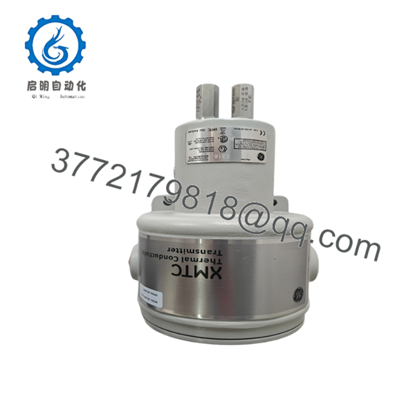
| Product Type | Thermal Conductivity Gas Transmitter |
| Measurement Principle | Thermal Conductivity |
| Application | Binary Gas Analysis |
| Typical Gas Pairs | H₂/N₂, CO₂/Air, CH₄/CO₂, He/N₂ |
| Analog Output | 4–20 mA |
| Digital Communications | RS232, RS485 |
| Sensor Technology | Glass-coated thermistor elements |
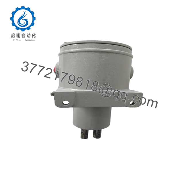
| Housing Type | Explosion-proof enclosure |
| Enclosure Materials | 316 Stainless Steel, Viton seals |
| Temperature Rating | Up to 65 °C ambient (T5 rated enclosure) |
| Certifications | CE compliant variants available |
| Typical Industries | Power generation, chemical processing, gas production, heat treatment |
| Product Status | Discontinued by OEM |
The XMTC series was designed for online gas concentration measurement in binary gas mixtures using thermal conductivity principles. Exact measurement range, gas calibration, and hazardous-area approvals depend on the specific XMTC configuration ordered from the factory. Verify the original Panametrics nameplate before installation.
4. Product Introduction
The GE Panametrics XMTC-62-21 is an online thermal conductivity gas transmitter used to measure the concentration of a target gas within a binary gas mixture. Common applications include hydrogen monitoring in generator cooling systems, hydrogen concentration measurement in furnace atmospheres, gas purity verification, and process gas analysis.
Unlike electrochemical or infrared analyzers, the XMTC uses thermal conductivity measurement with microprocessor-based signal processing and glass-coated thermistor technology. In power plants and chemical facilities, engineers often selected this platform because it provided continuous measurement without moving parts and could integrate directly into DCS or PLC systems through 4–20 mA and serial communications.
-

- XMTC-62-21
- XMTC-62-21
5. Installation & Configuration Guide
Stage 1: Pre-Installation Preparation (10 Minutes)
⚠️ Safety First
- Notify operations personnel of the planned outage.
- Confirm process isolation and safe operating conditions.
- Apply Lockout/Tagout (LOTO).
- Isolate transmitter power.
- Isolate process gas if maintenance requires opening the analyzer enclosure.
- Wait at least 5 minutes before handling internal electronics.
Tools Required
- ESD wrist strap
- PH1 screwdriver
- Fluke 115 multimeter
- Wire markers
- Smartphone camera
- Manufacturer wiring diagrams
Data Backup
- Record current calibration values.
- Record gas range settings.
- Document serial communications parameters.
- Photograph all terminal connections.
- Photograph internal jumper and DIP switch positions.
- Save DCS scaling values for the 4–20 mA loop.
Stage 2: Removing the Old Module (10 Minutes)
- Remove enclosure cover.
- Label all field wiring.
- Disconnect power wiring.
- Disconnect communication wiring.
- Disconnect analog output wiring.
- Remove mounting hardware.
- Carefully remove the transmitter.
⚠️ Note
Retain the original transmitter until the replacement has completed calibration verification and operational testing.
Inspection Checklist
- No corrosion inside enclosure
- No moisture ingress
- Cable glands intact
- Grounding conductors secure
- Shield terminations documented
Stage 3: Installing the New Module (10 Minutes)
Steps
- Wear ESD protection before handling electronics.
- Verify the exact model:
- XMTC-62-21
- Configuration Clone (Critical)
- Duplicate all jumpers.
- Duplicate communication settings.
- Verify gas range configuration.
- Mount the transmitter securely.
- Reconnect field wiring.
- Verify earth grounding.
- Tighten terminals to manufacturer torque recommendations.
Self-Checklist
- Model verified
- Configuration duplicated
- Communication settings matched
- Wiring secured
- Grounding verified
Stage 4: Power-On & Testing (15 Minutes)
Pre-Power Check
- Verify power supply voltage.
- Check loop continuity.
- Verify communication cable polarity.
- Confirm shield grounding.
Power-Up Sequence
- Energize transmitter power.
- Observe startup diagnostics.
- Verify display and status indicators.
- Connect maintenance software if applicable.
- Verify communication with PLC or DCS.
- Confirm 4–20 mA scaling.
- Introduce calibration gas if required.
- Verify measurement stability.
⚠️ Troubleshooting Note
- Communication failure: Verify RS232/RS485 settings.
- Incorrect readings: Check gas calibration setup.
- Output fixed at 4 mA or 20 mA: Verify sensor status and range configuration.
- Slow response: Check sample system filters and flow rates.
SOP Quality Transparency
1. Inbound Inspection & Traceability
Each XMTC-62-21 undergoes:
- OEM label verification
- Serial number recording
- Anti-counterfeit inspection
- Visual examination for:
- Corrosion
- Moisture ingress
- UV discoloration
- Mechanical damage
- Accessory verification
2. Live Functional Testing
Testing is performed using a dedicated analyzer simulation platform.
Procedures include:
- Power-on self-test verification
- Display diagnostics check
- 4–20 mA loop simulation
- RS232 communication verification
- RS485 communication verification
- Continuous operation exceeding 24 hours
- Temperature monitoring during operation
A formal test report is generated upon request.
3. Electrical Parameter Testing
- 500 V insulation resistance test (>10 MΩ)
- Ground continuity test
- Power supply verification
- Output loop validation
4. Firmware & Configuration Verification
- Firmware revision documented
- Configuration settings recorded
- DIP switch positions photographed
- Calibration settings archived
5. Final QC & Packaging
- Inspector sign-off
- Anti-static protection
- Shock-resistant packaging
- Heavy-duty export carton
- QC Passed label with inspection date
Test photos and operational videos are available upon request.
Technical Pitfall & Survival Guide
❗ Firmware Revision Mismatch
I’ve seen analyzer replacements consume an entire shutdown weekend because nobody checked firmware revisions.
The replacement powered up, but the DCS refused communications.
Avoidance:
- Record firmware version before removal.
- Request firmware verification when ordering.
- Verify protocol compatibility before shipment.
❗ DIP Switch / Jumper Misconfiguration
This is the most common rookie mistake, but it happens in experienced crews too.
Take a picture before you pull it. I can’t stress this enough.
Avoidance:
- Photograph every switch position.
- Document communication parameters.
- Match all jumper settings exactly.
❗ Terminal Block / Wiring Incompatibility
I’ve encountered replacement analyzers where terminal numbering changed between revisions.
The wiring looked correct. The signal was not.
Avoidance:
- Verify every terminal against the manual.
- Confirm analog output polarity.
- Confirm communication wiring polarity.
❗ Power Supply Loading
Analyzer loops are often added to already crowded instrument power supplies.
A transmitter may work on the bench but become unstable in the field due to voltage drop.
Avoidance:
- Verify available power capacity.
- Maintain a minimum 20% supply margin.
- Measure voltage under load.
❗ Electrostatic Discharge (ESD)
I once watched a contractor unpack an analyzer directly on a painted steel table during winter.
The transmitter powered up but never produced stable measurements.
Avoidance:
- Wear a grounded wrist strap.
- Use ESD-safe work surfaces.
- Keep electronics protected until installation.
Keep these checks in mind and you’ll save yourself 90% of typical rework time.
6. Frequently Asked Questions (FAQ)
Q1. Can I hot-swap the XMTC-62-21 under power?
No.
This transmitter should be isolated from power before removal. Disconnecting field wiring under power can create communication faults, calibration issues, or damage electronics in hazardous-area installations.
Q2. Is the XMTC-62-21 obsolete?
Yes.
The XMTC-62-21 is generally considered a discontinued legacy Panametrics analyzer platform. Most available units today come from surplus inventories, strategic spares programs, or tested refurbished stock.
Q3. Is this a gas analyzer or a conductivity transmitter?
Both descriptions are used.
The instrument measures gas concentration using thermal conductivity technology. In practice, engineers often refer to it as a thermal conductivity gas analyzer or thermal conductivity transmitter.
Q4. Will I lose calibration data when replacing the transmitter?
Possibly.
Always document:
- Calibration ranges
- Gas composition settings
- Alarm points
- Output scaling
- Communication settings
Failure to do so can extend commissioning time considerably.
Q5. What is the direct replacement if this model is unavailable?
There is no universal drop-in replacement.
Replacement selection depends on:
- Gas composition
- Hazardous-area classification
- Required accuracy
- Existing DCS integration
Verify the original Panametrics configuration sheet before selecting a successor model.
Q6. Why is the price lower than historical OEM pricing?
Most available inventory is surplus stock or secondary-market inventory rather than current factory production.
Pricing reflects market availability, condition, testing status, and remaining inventory levels rather than original GE list pricing.
Q7. What condition is typically available?
Most suppliers offer one of the following:
- New Original (New Surplus)
- Unused Surplus
- Refurbished (Tested)
- Removed Working Spare
Always request:
- Actual photographs
- Serial number verification
- Test reports
- Warranty details
For discontinued analyzers, documentation quality is often more valuable than a small difference in purchase price.


