
 WhatsApp: +86 16626708626
 Email:
  Phone: +86 16626708626
Description
Key Technical Specifications
| Parameter | Value |
|---|---|
| Manufacturer | Siemens / GEA Westfalia Separator OEM variant |
| OEM Part Number | 0005-4050-430 |
| Siemens Equivalent | SIMATIC C7-613 (6ES7613 series family) |
| Controller Type | Integrated HMI + PLC compact unit |
| PLC CPU | Siemens S7-300 CPU313C |
| Power Supply | 24 VDC |
| Digital Inputs | 24 channels, 24 VDC |
| Digital Outputs | 16 channels, 24 VDC, 0.5 A |
| Analog Inputs | 5 channels |
| Analog Outputs | 2 channels |
| Display | 4-line LCD operator display |
| Operator Interface | Integrated keypad |
| Required Memory | Micro Memory Card |
| Operating Temperature | 0 °C to +50 °C |
| Application | GEA Westfalia separator control |
| Product Lifecycle | Discontinued / legacy equipment |
The 0005-4050-430 is commonly identified as a GEA Westfalia Separator Control Module based on the Siemens SIMATIC C7-613 platform. References associate it with a GEA separator application and list integrated S7-300 CPU313C functionality with digital and analog I/O.
Product Introduction
The 0005-4050-430 is a GEA Westfalia Separator control module built around the Siemens SIMATIC C7-613 compact automation platform. It combines an operator display, keypad, Siemens S7-300 CPU313C PLC functions, and integrated I/O for separator machine control applications.
This unit was designed for installed GEA separator systems where replacing the complete controller is usually preferred over rebuilding the control architecture. Because it contains both PLC logic and operator interface functions, compatibility depends on the existing project backup, memory card contents, and machine-specific configuration.
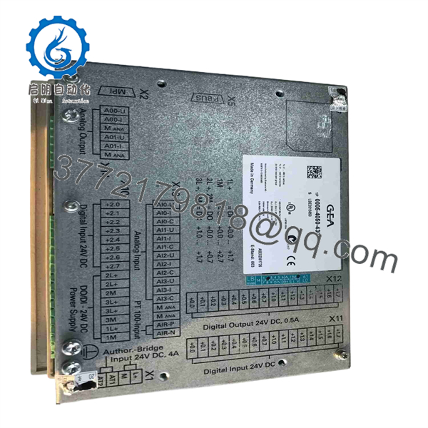
0005-4050-430
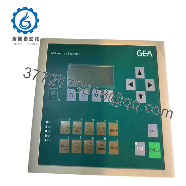
0005-4050-430
Installation & Configuration Guide
Stage 1: Pre-Installation Preparation (~10 minutes)
- Notify operations personnel about the planned shutdown.
- Apply lockout/tagout procedures before opening the control cabinet.
- Verify the 24 VDC supply is isolated.
- Wait for stored energy discharge before touching internal electronics.
Tools Required:
- ESD wrist strap
- PH1 screwdriver
- Digital multimeter
- Wire labels
- Smartphone/camera for documentation
Data Backup:
- Save the existing Siemens STEP 7 project if available.
- Remove and preserve the original Micro Memory Card.
- Photograph:
- Terminal wiring
- Connector positions
- Device labels
- Hardware revision markings
- Record machine parameters and alarm settings.
⚠️ Do not remove the memory card before documenting its condition. The PLC program and configuration may depend on the original card.
Stage 2: Removing the Old Module (~10 minutes)
- Remove the cabinet access cover.
- Label every connected wire before disconnecting.
- Disconnect power and communication wiring carefully.
- Release the mounting clips or fixing hardware.
- Remove the C7-613 unit straight from the mounting position.
- Inspect connectors for oxidation, loose pins, or contamination.
⚠️ Keep the original controller until the replacement has completed testing.
Stage 3: Installing the Replacement (~10 minutes)
- Wear ESD protection before handling the replacement unit.
- Verify the full ordering code:
0005-4050-430
- Compare:
- Front display
- Keypad layout
- Connector arrangement
- Hardware revision
- Transfer the original Micro Memory Card if required.
- Install the replacement controller.
- Reconnect all wiring according to photographs.
- Check 24 VDC polarity before power application.
Self-Checklist:
- Correct part number verified
- Memory card installed
- Wiring checked
- Power polarity confirmed
- Mechanical mounting secured
Stage 4: Power-On & Testing (~15 minutes)
- Measure the 24 VDC supply before startup.
- Power the controller.
- Check display initialization.
- Verify PLC RUN status.
- Check for diagnostic faults.
- Confirm digital input operation.
- Test digital outputs under controlled conditions.
- Verify analog channel readings.
- Run separator commissioning tests.
- Record final operating parameters.
Technical Pitfall & Survival Guide
❗ Firmware and program compatibility is the first replacement risk.
A physically identical C7-613 can still fail startup if the PLC project version, memory card contents, or hardware configuration differs.
I have seen legacy Siemens compact controllers replaced successfully from a hardware perspective, only to stop production because nobody preserved the original Micro Memory Card. The lesson is simple: save the software before touching the hardware.
❗ Do not wire from memory.
Even within Siemens compact controllers, terminal assignments and integrated I/O configurations vary by model. Always compare the wiring diagram with the actual unit.
❗ Check power consumption before replacement.
A replacement controller drawing more current than the original can overload an existing 24 VDC supply, especially in older separator cabinets where the power margin was limited.
Frequently Asked Questions (FAQ)
What is Siemens 0005-4050-430?
The 0005-4050-430 is a GEA Westfalia Separator control module using the Siemens SIMATIC C7-613 platform. It combines PLC control and operator interface functions.
Is 0005-4050-430 the same as a Siemens C7-613?
It is based on the Siemens C7-613 family, but the 0005-4050-430 is a GEA-specific OEM configuration. Do not replace it with a standard C7-613 without verifying the project, I/O configuration, and machine application.
Is this model obsolete?
Yes. The C7-613 platform is a legacy Siemens product family, and the 0005-4050-430 is mainly available through industrial spare-parts channels. Treat it as a maintenance replacement component rather than a new-system selection.
Will I lose the PLC program when replacing this module?
Not necessarily. The program may be stored on the Micro Memory Card or require transfer from the original STEP 7 project. Always preserve the original card and backup files before replacement.
Can I use a normal Siemens C7-613 instead of 0005-4050-430?
Not automatically. GEA separator systems often include OEM-specific configuration, hardware settings, and application software. Verify compatibility before substitution.
Why is the price lower than a new Siemens controller?
Because this is a discontinued industrial component. Available units typically come from surplus inventory, repaired stock, or tested refurbished channels rather than current production.
What should I verify before purchasing?
Confirm:
- Full part number: 0005-4050-430
- Hardware revision
- Display condition
- Keypad condition
- 24 VDC power test results
- Micro Memory Card availability
- GEA separator model compatibility
- Functional test report
For surplus equipment, request inspection photos and test records. Avoid purchasing only by model number because legacy C7 systems often contain application-specific configurations.



