
 WhatsApp: +86 16626708626
 Email:
  Phone: +86 16626708626
Description
Key Technical Specifications
| Parameter | Value |
|---|---|
| Manufacturer | GESAS GmbH |
| Model Number | CAN-DPV |
| Product Type | Digital amplifier / proportional-valve control module |
| Primary Function | Converts CAN network commands into controlled actuator-drive outputs |
| Communication Interface | CAN bus |
| CAN Physical Layer | Verify whether the installed system requires isolated CAN and its exact termination scheme |
| Nominal Supply | 24 V DC nominal; verify the exact acceptable input range from the installed-system documentation |
| Controlled Load Type | Proportional hydraulic valves, solenoid coils, or other application-specific actuators |
| Output Method | PWM-controlled actuator output; output-current rating must be confirmed against the actual unit label or OEM manual |
| Configuration Items | CAN node ID, CAN baud rate, output parameters, and any hardware switches or jumpers |
| Mounting | Control-enclosure installation; verify mounting and connector orientation against the removed unit |
| Lifecycle Status | Legacy / obsolete industrial automation component |
| Weight | Approximately 0.3–0.4 kg in third-party listings; verify against actual supplied unit |
| Environmental Claims | Third-party listings cite 0 to 55 °C and 10–95% RH non-condensing; treat as unverified until confirmed by OEM documentation |
The available public information consistently identifies CAN-DPV as a GESAS GmbH PLC/machine-control module. Several third-party listings describe it as a CAN-networked digital amplifier or control module, but exact electrical ratings, connector pinout, current capacity, firmware, and mechanical dimensions are not established by an accessible OEM datasheet. Verify those items before connecting field wiring or ordering a replacement.
Product Introduction
The GESAS CAN-DPV is a legacy digital amplifier and control module used where a CAN network commands proportional valves, hydraulic actuators, or similar field devices. The module belongs in an existing GESAS-based control assembly and should be replaced only with an exact CAN-DPV match after checking the original unit’s labels, wiring, and configuration.
The primary purchase case is restoring an installed machine without redesigning its CAN control architecture. Correct node address, bus rate, 120 Ω termination, supply polarity, valve-coil ratings, and connector pinout matter more than the board’s appearance. A wrong setup can produce a network fault, uncontrolled output behavior, or no actuator response.
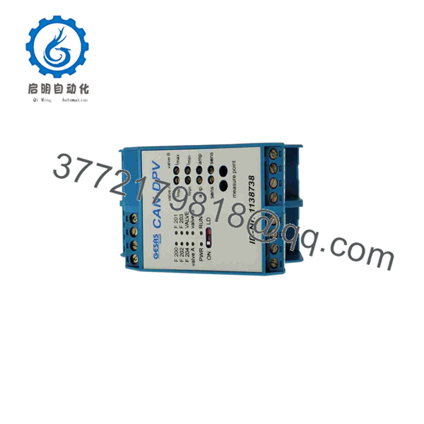
CAN-DPV
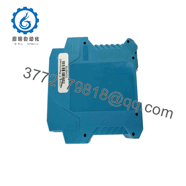
CAN-DPV
Troubleshooting Quick Reference
| Symptom | Possible Cause | Relevance to This Part | Quick Check Method | Recommendation |
|---|---|---|---|---|
| No status LEDs after power-up | Missing 24 V DC supply, blown cabinet fuse, reverse polarity, poor connector contact | ❌ Low to medium | With the cabinet drawing in hand, measure the DC supply at the CAN-DPV power connector; confirm polarity and voltage under load | Repair the supply, fuse, wiring, or connector before replacing the module |
| CAN network offline or communication timeout | Broken CAN-H/CAN-L conductor, missing termination, duplicate node ID, wrong baud rate | ⚠️ Medium | Check CAN-H and CAN-L continuity with power removed; inspect both end-of-line terminations; compare node settings with the previous unit | Confirm bus wiring, 120 Ω termination placement, node ID, and baud rate before condemning CAN-DPV |
| Controller sees the node but actuator does not move | Disabled output, missing hydraulic pressure, broken coil, open field fuse, failed relay | ❌ Low to medium | Confirm command state in the master controller; measure voltage at the valve coil; check coil resistance against the valve manufacturer’s value | Diagnose the field device, valve coil, fuse, and hydraulic circuit before replacing CAN-DPV |
| Output remains at zero despite valid CAN command | Incorrect configuration, output inhibit, failed output stage, incompatible replacement revision | ✅ High | Compare parameters, DIP switches, jumpers, and label revisions with the removed module; monitor output command and actual output voltage | Restore the original configuration; if command is present but output is absent, replace after confirming load wiring |
| Actuator hunts, jerks, or moves unevenly | Incorrect PWM parameters, unstable supply, bad feedback signal, hydraulic issue | ⚠️ Medium | Monitor 24 V DC supply during actuation; inspect feedback wiring and shielding; compare settings with a known working axis | Check configuration and hydraulic condition before replacing the amplifier module |
| Module or valve coil overheats | Shorted coil, excessive current demand, incorrect PWM setup, blocked valve | ⚠️ Medium | Power down, disconnect the load, measure coil resistance, inspect for short-to-ground, and compare against approved load rating | Do not install another CAN-DPV until the coil and valve circuit pass inspection |
| Fault appears only after replacement | Wrong hardware revision, mismatched configuration, CAN address conflict, connector mismatch | ✅ High | Photograph the original module before removal; compare every connector, switch, jumper, and identification label | Match the original unit exactly and recheck commissioning parameters |
| Intermittent operation during vibration | Loose connector, damaged CAN cable, oxidized contacts, weak power terminal | ❌ Low to medium | With equipment safe, inspect connector retention, cable strain relief, terminal torque, and enclosure grounding | Correct mechanical and wiring defects before ordering a replacement |
❗ Firmware and configuration mismatch: Document the old module before pulling it. A replacement with a different firmware behavior, CAN node setting, or output parameter set can show up as a network fault even though the hardware powers up normally. I have seen commissioning teams lose two shifts to a “bad” replacement that only had the wrong baud rate.
❗ DIP switches and jumpers: Take high-resolution photos of both sides of the original CAN-DPV before removal. This is the most common avoidable mistake. Address selection, termination, output mode, or service settings may be physical, not software-defined.
❗ CAN bus termination: Do not add terminators everywhere. A standard CAN trunk normally uses one 120 Ω terminating resistor at each physical end of the bus. Incorrect termination can create intermittent communication failures that look exactly like a defective control module.
❗ Valve wiring and output load: Do not wire from memory. Check coil polarity, pinout, shielding, and coil resistance against the machine schematic. A shorted proportional-valve coil can destroy a replacement output stage quickly.
❗ ESD controls: Wear a grounded wrist strap and store the replacement in ESD-safe packaging until installation. I once watched a technician handle an expensive control card in dry winter air without a strap; it powered up once, then failed under load. Use the strap.
If the fault remains unclear, send technical support photos of the original and replacement labels, all switch settings, the cabinet wiring diagram, CAN diagnostics, LED states, and measured supply voltage. Keep these checks in mind and you will save yourself 90% of typical rework time.
Frequently Asked Questions
Is the GESAS CAN-DPV a direct replacement for my existing module?
Only if the installed device is marked CAN-DPV and the connectors, hardware revision, pinout, CAN configuration, and application match. Do not substitute based only on the housing or a similar-looking GESAS control board. Compare clear photos of the original board, including all labels and switches, before ordering.
Is CAN-DPV obsolete, and is stock limited?
Yes. CAN-DPV is commonly treated as a legacy GESAS industrial automation part, so availability depends on surplus inventory or tested used units. Confirm actual stock, condition, unit photographs, lead time, and warranty before committing to a shutdown plan.
Can I hot-swap the CAN-DPV module?
No—do not assume hot swapping is permitted. Unless the machine manufacturer’s documentation specifically approves it, isolate the control supply, apply lockout/tagout procedures, and verify the circuit is de-energized before removal. Pulling a CAN-linked amplifier under power can corrupt network communications, damage the connector, or energize an actuator unpredictably.
Do I need to configure CAN settings after replacing the module?
Usually, yes. At minimum, verify the node ID, baud rate, CAN termination state, and application-specific output settings. Before removal, record the old unit’s switches, jumper positions, controller parameters, and any diagnostic data. A new module with a duplicate address or wrong bus speed can hold up the entire network.
Will replacing CAN-DPV retain my machine settings?
Do not count on it. Depending on the system design, parameters may reside in the CAN-DPV, a master PLC, an HMI, or an external configuration tool. Save the available configuration first, photograph the hardware settings, and confirm how the machine stores valve calibration and output parameters. To be honest, legacy CAN systems can be a hassle when no one saved the original commissioning files.
Why is a New Surplus CAN-DPV less expensive than a factory-supplied part?
New Surplus means unused inventory that entered the secondary market after original procurement, project cancellation, excess spares liquidation, or equipment decommissioning. It may be genuine and unused, but it is not necessarily supplied through the original factory channel. Ask for actual-item images, serial or date-code photos where appropriate, packaging details, inspection results, and written warranty terms.
What testing should I request before purchase?
Request evidence that the unit was checked for physical condition, connector integrity, correct identification, power-up status, CAN communication, and output behavior under a suitable simulated load. For a credible test process, the supplier should be able to provide photos or video on request, document the test environment, verify current hardware markings, and issue a functional test report. Public third-party descriptions identify CAN-DPV as a CAN-enabled control module, but its specific electrical ratings and pinout still require confirmation against your original system documentation.



