
 WhatsApp: +86 16626708626
 Email:
  Phone: +86 16626708626
Description
Key Technical Specifications
| Parameter | Value |
|---|---|
| Manufacturer | GESPAC |
| Model | GESVIG-4W |
| Board designation | VIG-4W |
| Product type | Composite video graphics board |
| Primary function | Video graphics control/processing |
| Application | Industrial computer and control equipment |
| Board variant | GESVIG-4W/9340 is documented |
| Related reference | VIG-4W 9340 |
| Example PCB marking | CIRELEC / A94-V0 markings reported on a GESVIG-4W/9340 board |
| Example serial | SN 101129G reported for one 9340 unit |
| Lifecycle status | Legacy / specialist replacement market |
| Mounting | PCB/card installation; exact chassis/backplane compatibility must be verified |
The available documentation is limited compared with current PLC and DCS hardware. A third-party GESPAC component catalog identifies GESVIG-4W specifically as a “Video Graphics Controller,” while another industrial parts source describes it as a “Composite Video Graphics Board.”
Do not substitute specifications from unrelated GESPAC modules. In particular, some online listings incorrectly classify the GESVIG-4W as a generic industrial control module and publish electrical specifications that conflict with the component descriptions above. Those specifications should not be used for engineering replacement decisions.
Product Introduction
The GESPAC GESVIG-4W is a legacy GESPAC video graphics board used for graphics/video functions within industrial computer and control equipment. Available component catalogs identify it as a video graphics controller, while specialist industrial suppliers identify the VIG-4W as a composite video graphics board.
For replacement work, the exact board revision is important. Variants such as have been documented with additional PCB and serial-number markings, so procurement should compare the complete board label rather than relying only on the base designation.
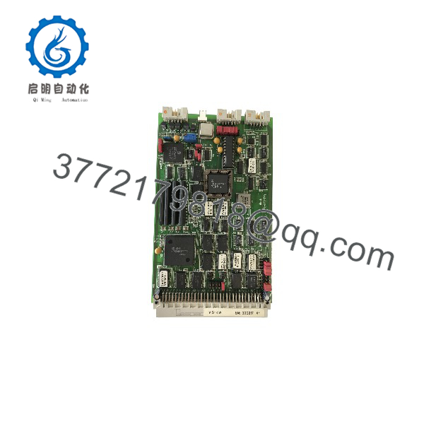
GESVIG-4W
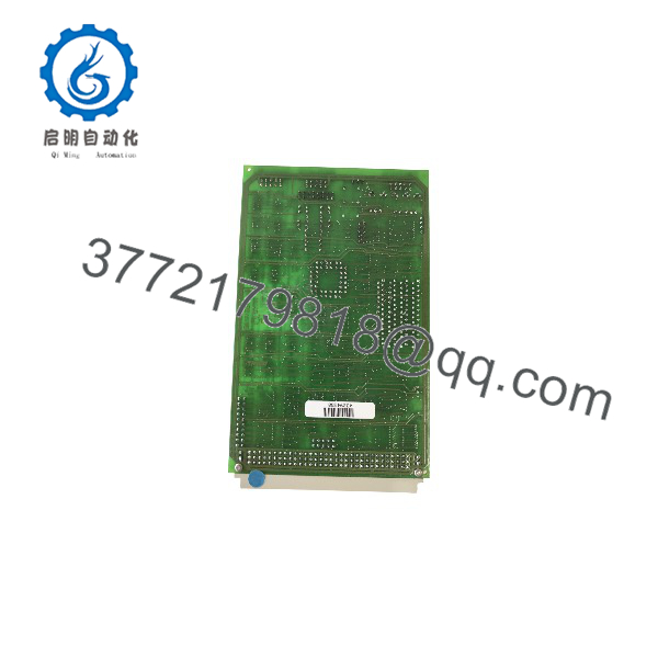
GESVIG-4W
Installation & Configuration Guide
Step 1 — Pre-Installation Inspection
- Record the installed board’s complete part number, revision, serial number, and PCB markings.
- Photograph the existing board before removal.
- Confirm whether the installed unit is marked , VIG-4W, or a variant such as .
- Verify the host chassis, backplane, connector arrangement, and board position.
- Save any system configuration or display settings that may reside in the host computer.
Warning: Do not assume that two boards with the same base number are electrically identical. Revision and assembly markings should be matched before installation.
Step 2 — Remove the Existing Board
- Shut down the host equipment according to the equipment manufacturer’s procedure.
- Isolate the system from hazardous power where applicable.
- Allow the equipment to discharge before accessing the PCB.
- Use appropriate ESD protection.
- Disconnect external video or interface connections.
- Release the board retaining hardware.
- Pull the card straight from its connector without twisting it.
Step 3 — Inspect and Install the Replacement
- Compare the replacement board against the removed .
- Check the connector keying and board-edge contacts.
- Compare jumper, switch, and configuration positions if fitted.
- Inspect the PCB for corrosion, damaged components, bent pins, or contaminated contacts.
- Install the board into the same chassis/backplane position unless the equipment documentation specifies otherwise.
- Secure the board mechanically.
- Reconnect the video and associated interface connections.
Step 4 — Power-On and Functional Test
- Restore power to the host system.
- Observe the initial system diagnostics.
- Confirm that the graphics/video subsystem initializes.
- Verify the expected display output.
- Check for abnormal artifacts, missing video, incorrect synchronization, or intermittent operation.
- Run the host equipment’s normal operating sequence.
- Record the replacement board’s revision and serial number for maintenance records.
Replacement Troubleshooting
No video after replacement
- Confirm the board is fully seated.
- Recheck connector orientation and board position.
- Compare configuration hardware with the original board.
- Verify the host system recognizes the graphics subsystem.
- Check the external display/video path.
Video is unstable or incorrect
- Compare the replacement board revision with the original.
- Inspect connector contacts.
- Check configuration settings.
- Verify that the replacement board is the correct VIG-4W variant rather than another GESPAC graphics assembly.
System fails to initialize
- Remove power and reseat the board.
- Check for bent or damaged connector contacts.
- Confirm that the host backplane is compatible.
- If the original board is available, compare PCB markings and configuration hardware directly.
FAQ
Is GESPAC a PLC I/O module?
No. Available GESPAC component documentation identifies the as a Video Graphics Controller, while specialist parts catalogs describe it as a Composite Video Graphics Board. It should therefore be treated as a graphics subsystem board rather than a conventional PLC analog or digital I/O module.
What is the /9340 designation?
appears in secondary-market listings as a specific board variant. One documented unit carries the references VIG-4W, 9340, -9340, and additional PCB/serial markings.
Is the obsolete?
It appears to be a legacy component rather than a mainstream current-generation industrial controller. Specialist obsolescence-management suppliers continue to list it, generally on an availability/on-demand basis.
Can I replace any with a /9340?
Do not assume direct interchangeability solely from the base model number. Compare the complete assembly number, revision, PCB markings, connector configuration, and host-system requirements before installing the replacement.
Does the require programming?
The available public sources do not provide sufficient documentation to establish a programming procedure or firmware-loading process for every revision. Treat configuration and firmware compatibility as equipment-specific until confirmed from the original system documentation.
What should I provide when requesting a replacement?
Provide a clear photograph of the board label and PCB, including the / designation, revision, assembly number, serial number, and visible component markings. This is particularly important because documented units carry additional identifiers such as 9340 and different PCB markings.
What condition should I expect from the replacement market?
Condition varies. Some suppliers list the as available on demand, while other listings identify specific used or surplus assemblies. Confirm whether the offered board is new old stock, refurbished, tested used, or untested before purchase.



