
 WhatsApp: +86 16626708626
 Email:
 Phone: +86 16626708626
Description
Core Product Summary (Brand / Model / Key Attributes)
The GUTOR 0400011 (also marked as PCA ISO-Driver and associated with SILCON 21060-4) is an industrial printed circuit board assembly engineered for deployment within GUTOR uninterruptible power supply (UPS), rectifier, and static switch (SL/SSW) power conversion systems. Serving as an isolated driver subassembly, this board transmits electrical gate or switching control signals between low-voltage control logic and high-power semiconductor stages while maintaining galvanic isolation.
Built for continuous industrial power infrastructure, the module incorporates on-board signal isolation components, capacitive decoupling, and standardized multi-pin board connectors configured for integration into compatible GUTOR power conversion racks and enclosures. Proper installation requires strict adherence to electrostatic discharge (ESD) protocols, verification of board revision and connector alignment, and complete isolation of system power prior to service.
Key Technical Specifications
| Specification Category | Technical Detail |
|---|---|
| Manufacturer / Brand | GUTOR (Gutor Electronic) |
| Model / Order Number | 0400011 |
| Functional Designation | PCA ISO-Driver |
| Associated System Reference | SL / SSW / SILCON 21060-4 |
| Product Type | Isolated Driver Printed Circuit Board Assembly (PCBA) |
| Primary Application | Industrial UPS, Rectifier, and Static Switch Power Stages |
| Mounting Format | Internal Enclosure / Rack Subassembly Integration |
Detailed Product Overview
The GUTOR 0400011 functions as an isolated driver board within industrial power conversion architectures, including rectifiers, static switches, and SILCON-series UPS units. In high-power industrial conversion systems, driver subassemblies bridge the control electronics and the power switching stage, conditioning control pulses and providing electrical isolation to protect sensitive logic circuits from high-voltage transients.
Integrating or replacing this printed circuit assembly requires confirming exact part-number and board-designation alignment with the host equipment’s spare-parts documentation. Because isolated driver boards interface directly with power semiconductor circuits, technicians must ensure all multi-pin connectors and ribbon harnesses are clean, properly keyed, and fully seated before energizing the system.
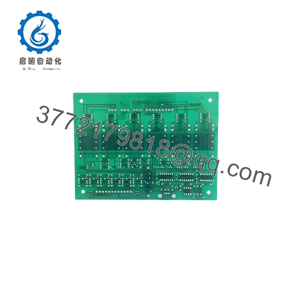
0400011
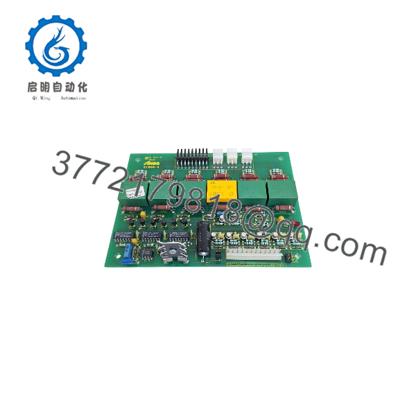
0400011
Engineering Selection Highlights
- Exact Part Identification: Identified by order number 0400011 and board marking PCA ISO-Driver (SILCON 21060-4), supporting accurate spare-part matching for compatible GUTOR power systems.
- Isolated Driver Function: Designed to provide electrical isolation and drive-signal conditioning for rectifier and static switch (SL/SSW) power stages.
- Dedicated System Integration: Features board-mounted multi-pin connectors and discrete isolation components tailored for direct placement inside designated GUTOR power conversion chassis.
- Maintenance and Lifecycle Support: Serves as a direct replacement subassembly for corrective maintenance and spare-parts inventory in established industrial UPS installations.
System Compatibility & Integration Requirements
| Item / Dependency | Verified Compatibility or Requirement | Practical Note |
|---|---|---|
| System Family | GUTOR UPS, Rectifier, and Static Switch (SL/SSW / SILCON) Systems | Cross-check the host cabinet’s parts list and silk-screened board references (0400011 / 21060-4) prior to installation. |
| Mounting Interface | Internal Chassis / Power Stage Mounting Points | Secure the PCB properly on its designated standoffs or card guides to maintain electrical clearance. |
| Connection Protocol | On-Board Multi-Pin Connectors and Wiring Harnesses | Confirm proper connector orientation and full mechanical engagement before applying power. |
Dimensions, Mounting & Connection Notes
- Mounting Configuration: Designed for internal installation within designated GUTOR power electronics enclosures using factory mounting hardware or card guides.
- Handling Precautions: Observe strict electrostatic discharge (ESD) precautions, including grounded wrist straps and static-dissipative work surfaces, whenever handling the unmounted board.
- Electrical Isolation Safety: Ensure all AC, DC, and battery power sources are isolated and locked out before installing or removing the board, as driver circuits interface with high-voltage power stages.
- Environmental Limits: Intended for operation inside clean, climate-controlled industrial cabinets protected from moisture, conductive dust, and corrosive atmospheres.
FAQ
What is the GUTOR 0400011?
The GUTOR 0400011 is an isolated driver printed circuit board assembly (PCA ISO-Driver) used in GUTOR industrial power conversion and UPS equipment.
Which systems use the GUTOR 0400011 board?
It is associated with GUTOR SILCON (21060-4), rectifier, and static switch (SL/SSW) power systems.
What is the role of an ISO-Driver board in a UPS or rectifier?
An ISO-Driver board transfers switching control signals from the control logic to the power semiconductor stage while maintaining electrical isolation between high-voltage and low-voltage circuits.
What precautions are required when replacing this board?
Technicians must de-energize and lock out all power sources, verify zero residual voltage on DC bus capacitors, use ESD-protective equipment, and verify exact connector alignment before re-energizing.
Verification & Troubleshooting Notes
- Visual Inspection: Prior to installation, inspect the PCB for damaged components, cracked solder joints, heat discoloration, or bent connector pins.
- Connector and Harness Check: Verify that all multi-pin plugs and signal harnesses are firmly seated on the correct headers without bent pins or loose wires.
- Post-Installation Verification: Following manufacturer commissioning procedures, monitor system startup diagnostics and status indicators to confirm normal gate-drive and power-stage operation before transferring critical loads.



