
 WhatsApp: +86 16626708626
 Email:
  Phone: +86 16626708626
Description
3. Key Technical Specifications
| Parameter | Value |
|---|---|
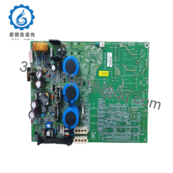
| Model Number | 0P0280 |
| Manufacturer | GUTOR |
| Product Type | AC Power Supply Unit PCB |
| Description | PSU AC Supply Module |
| Output Voltage 1 | +20 VDC |
| Output Voltage 2 | +12 VDC |
| Output Voltage 3 | −12 VDC |
| Output Voltage 4 | +5 VDC |
| System Application | Industrial UPS / Power Systems |
| Installation Type | PCB assembly installation |
| Approximate Weight | 1 kg |
| PCB Type | Power conversion board |
| ESD Handling | Mandatory |
| Condition | New Original / New Surplus |
| Warranty | 12 months |
Available technical references identify 0P0280 as a power supply assembly with output rails of +20 VDC, ±12 VDC, and +5 VDC, used in GUTOR power systems and UPS-related applications.
4. Product Introduction
The GUTOR 0P0280 is a PCB-based AC power supply module used within industrial power and UPS architectures. It converts incoming AC power into multiple regulated DC outputs used by control electronics and support circuitry. Available references identify output rails of +20 VDC, +12 VDC, −12 VDC, and +5 VDC.
In field deployments, these power modules often create misleading symptoms when they begin failing. I’ve watched maintenance teams troubleshoot communication faults and controller alarms for hours, only to discover a marginal ±12 V rail drifting under load. Power supplies fail quietly. They rarely announce themselves.
5. Installation & Configuration Guide
Stage 1: Pre-Installation Preparation (Estimated Time: 10 minutes)
⚠️ Safety First: Notify operations of downtime. Verify system safe state. Apply lockout/tagout procedures. Remove incoming power and wait 5 minutes for capacitor discharge.
Tools Required
- ESD wrist strap
- PH1 screwdriver
- Fluke 115 multimeter
- Wire labels
- Smartphone for photographs
- ESD work mat
Data Backup
- Document cabinet and slot location.
- Photograph connector positions.
- Record all wiring locations.
- Capture labels and board revision markings.
- Document terminal orientation.
⚠️ UPS systems accumulate undocumented field modifications. I’ve opened cabinets where the drawings and the hardware looked like two different systems.
Stage 2: Removing the Old Module (Estimated Time: 5 minutes)
- Open access covers.
- Label all wiring before disconnecting.
- Disconnect cables carefully.
- Release board retainers.
- Pull straight outward.
⚠️ Never force the board.
I watched a technician rush a board replacement and bend connector pins on a UPS backplane. The module swap took ten minutes. The cabinet repair consumed two days.
Inspect:
- Bent connector pins
- Corrosion
- Dust contamination
- Heat discoloration
- Loose hardware
⚠️ Keep the original module until startup verification completes.
Stage 3: Installing the New Module (Estimated Time: 5–10 minutes)
- Wear ESD protection before handling.
- Verify exact model: 0P0280
- Configuration Clone (Crucial): Duplicate jumpers and settings exactly if applicable.
- Align carefully with card guides.
- Insert evenly until fully seated.
- Reconnect all wiring.
Self-Checklist:
[ ] Board seated
[ ] Wiring secured
[ ] Hardware locked
[ ] Labels verified
⚠️ This is the most common rookie mistake, but it happens constantly. Take a picture before removal. I can’t stress this enough.
Stage 4: Power-On & Testing (Estimated Time: 10 minutes)
Pre-Power Check
Use a multimeter and verify no short condition exists.
Power-up sequence:
- Energize cabinet power only
- Observe startup indicators
- Measure DC output rails
- Verify +20 VDC
- Verify +12 VDC and −12 VDC
- Verify +5 VDC under load
⚠️ Troubleshooting Note:
If the system powers but communication faults appear randomly, check output rails under operating load. I’ve seen supplies pass idle testing and collapse under real conditions.
Technical Pitfall & Survival Guide
❗ Firmware Revision Mismatch
Power supply modules rarely have firmware issues directly, but replacement boards often enter systems with undocumented revisions.
Record board revision numbers before shutdown.
❗ DIP Switch / Jumper Misconfiguration
Some GUTOR hardware revisions include configuration jumpers.
Take photos first.
Factory settings may not match plant configuration.
❗ Terminal Block / Wiring Differences
Even similar PSU assemblies may change connector arrangements.
Verify:
- Pin orientation
- Wiring diagrams
- Grounding methods
- Connector keying
Never wire from memory.
❗ Power Budget Calculation
This catches engineers constantly.
Measure actual cabinet loading and maintain 20% spare capacity.
A replacement module may introduce different startup current behavior.
❗ ESD Damage
I once watched a board handled during winter maintenance without grounding protection. Powered up once and failed immediately.
That mistake cost several thousand dollars and delayed startup.
Use:
- Grounded wrist straps
- ESD-safe work surfaces
- Anti-static packaging
Keep these checks in mind and you’ll save yourself 90% of typical rework time.
- 0P0280
- 0P0280
6. Frequently Asked Questions (FAQ)
Q1: Can I hot-swap GUTOR 0P0280?
No.
Do not replace this board under power. Internal power supply circuits and backplane connections can suffer damage during live insertion.
Power down first.
Q2: What exactly does GUTOR 0P0280 do?
Available technical references identify it as a power supply module producing +20 VDC, ±12 VDC, and +5 VDC outputs for industrial systems and UPS architectures.
Q3: Is GUTOR 0P0280 obsolete?
Yes.
Most inventory now comes from surplus channels and industrial stock suppliers rather than active OEM manufacturing. Public inventory references list limited stock and secondary-market sourcing.
Q4: Is this really new inventory?
Usually “New Original” means unused OEM surplus inventory rather than current production.
Request:
- Serial numbers
- Packaging photos
- Date codes
- Functional test reports
Q5: Why do output rail problems create strange system behavior?
Because unstable supply voltages create misleading symptoms.
I’ve seen ±12 V rails drift under load and create communication faults, startup alarms, and intermittent controller resets.
Power quality problems can look like software failures.
Q6: Why is pricing inconsistent?
Surplus inventory pricing depends on traceability, condition, testing level, and stock availability. Public listings show refurbished inventory with pricing around USD 561–774, while availability and condition vary by supplier.
Q7: How do you verify inventory before shipment?
Inspection process:
- OEM source verification and traceability review
- Anti-counterfeit inspection and serial validation
- Visual inspection for corrosion, scratches, UV yellowing, and rework marks
- Functional power output testing
- Continuous load testing for over 24 hours
- 500 V Megger insulation test (>10 MΩ)
- QC sign-off and anti-static packaging
Test videos and photos are available upon request.


