
 WhatsApp: +86 16626708626
 Email:
  Phone: +86 16626708626
Description
3. Key Technical Specifications
- Part Number: 0P2552
- Alternate Number: 640‑2552 Rev 01
- Board Type: PCB Assy Power Connection Board
- Reference Designation: PCB ASSY PXP 312552010818047
- Reference Number: FKM7083M1 (board reference)
- Application: Used in GUTOR PXP / PxE AC UPS systems for 3‑phase power
- Mounting: Internal PCB within the UPS cabinet, typically mains‑input or bus‑connection position
- Electrical Role: Power connection and bus‑distribution PCB, not a control CPU
- Conformal Coating: Typical GUTOR UPS boards use conformal‑coated PCBs for environmental protection
- Condition in Market: Commonly sold as new‑original or open‑box, from surplus
4. Product Introduction
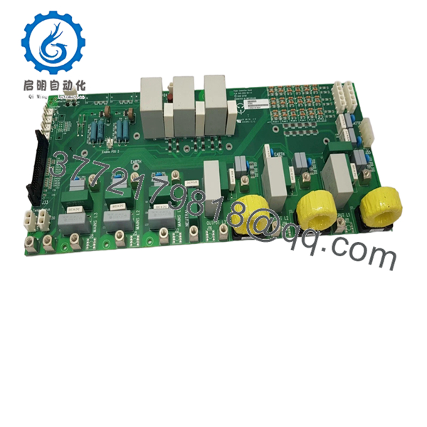
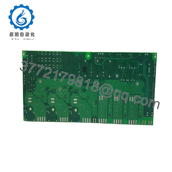
GUTOR 0P2552 is a power connection board PCB (640‑2552 Rev 01) used in GUTOR PXP‑series AC UPS systems. It handles the main power‑connection and bus‑distribution function inside the cabinet, so it is ordered as a replacement when the board is damaged, corroded, or shows signs of overheating near terminals.
Plant engineers typically swap this board when they see burnt traces, loose input‑bus connections, or repeated tripping related to the UPS power‑entry section. Because it is a power‑path PCB, installation demands solid mechanical and electrical checks: verify torque on input lugs, check for loose bus bars, and confirm the correct orientation before re‑energizing.
- 0P2552
- 0P2552
5. Troubleshooting Quick Reference
| Symptom | Possible Cause | Relevance to this Part | Quick Check Method | Recommendation |
|---|---|---|---|---|
| Input‑side breaker trips or upstream fuse blows | Internal short, damaged bus bar, or insulation failure on the board | ✅ High | Disconnect power; inspect PCB for burnt traces, cracked insulators, and scorch marks | If the board is visibly damaged, replace 0P2552 before re‑energizing |
| Output‑side voltage unbalanced or missing one phase | Loose bus connection or lifted trace on the board | ✅ High | Power‑off; check continuity and torque on bus bars and lugs | Tighten or re‑terminate; if traces are lifted, replace the board |
| UPS faults on “input‑fault” at startup but no fault upstream | Weak connection or tracking on the power‑connection board | ✅ Medium | Inspect for dust, moisture, or carbon tracks between phases/ground | Clean and dry; if tracking is present, replace 0P2552 |
| Intermittent fault when load changes | Loose bus bar or cracked solder joint near high‑current terminals | ✅ High | Check mechanical tightness and thermal camera scan under load | Replace if looseness or overheating is observed |
| No fault on board, but issues in downstream modules | Problem lies in rectifier, inverter, or configuration | ❌ Low | Check LEDs and alarms on control and power modules | Do not replace 0P2552 unless the board is physically or electrically damaged |
If the board is blackened, smelled of burnt electronics, or shows lifted traces, replacement is usually the only safe option. Contact technical support if you need photos interpreted or wiring confirmation.
6. Frequently Asked Questions
Q: Is 0P2552 still in production from GUTOR?
A: No. It is typically supplied from surplus‑stock channels as a genuine‑used or new‑surplus board, not from current OEM production runs.
Q: Can I use a different 0P board instead of 0P2552?
A: Not safely. 0P2552 is a specific power‑connection PCB for the PXP architecture; changing to a different 0P number may not match the bus layout or connector positions and could cause shorts or miswiring.
Q: Is this board new or refurbished?
A: In the market, 0P2552 generally ships as new original or open‑box surplus. For a product listing, explicitly state New Original or New Surplus, not “refurbished,” unless you have tested and rebuilt it.
Q: Why is this part so expensive?
A: Price reflects scarcity and demand in legacy PXP systems more than any exotic specs. Since it is a discontinued OEM board, options are limited and buyers pay a premium for a guaranteed‑fit spare.
Q: Can I hot‑swap this board?
A: No. This is a power‑connection PCB carrying mains voltage. De‑energize the UPS, lock out the input, and confirm the DC bus is discharged before removing or installing 0P2552.
Q: Will my UPS settings survive a swap?
A: Yes. The board is not a control or configuration store; it only routes power. Settings live in the control modules, not in this PCB. Just document terminal labels and torque values before removal.
Q: What should I check before ordering 0P2552?
A: Take a photo of the existing board label, confirm the PXP / UPS model number, and note the position (e.g., mains‑input connection board). Match the full 0P2552 and 640‑2552 Rev 01 designation exactly; even similar‑looking boards can differ in bus layout and connector polarity.



