
 WhatsApp: +86 16626708626
 Email:
  Phone: +86 16626708626
Description
3. Key Technical Specifications
| Parameter | Value |
|---|---|
| Model Number | 0P6267 |
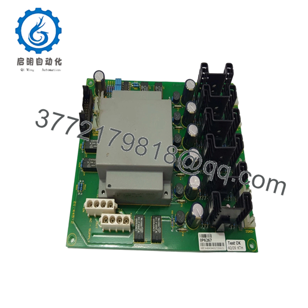
| Product Description | PCA ISODRIVER SDC-6P Circuit Board |
| Product Type | Industrial PCB Assembly |
| Application | UPS control and signal isolation |
| Platform | GUTOR Industrial UPS |
| Assembly Type | Internal chassis board |
| Board Function | Drive isolation and interface control |
| Installation | Internal rack/cabinet mount |
| Revision | Verify physical label before installation |
| Lifecycle Status | Legacy / surplus inventory market |
| Common Market Condition | New Surplus or Refurbished (tested) |
| OEM Origin | GUTOR Switzerland |
The exact electrical ratings are not publicly documented. Before scheduling downtime, verify board revision and connector identifiers from the physical assembly label. I’ve seen two boards carrying nearly identical labels but different connector assignments.
4. Product Introduction
The GUTOR 0P6267 is a PCA ISODRIVER SDC-6P circuit board used inside GUTOR industrial UPS systems. It functions as an internal control and isolation interface assembly supporting protected power infrastructure commonly deployed in oil and gas, utility, marine, and process-control environments.
In field deployments of industrial UPS cabinets, these boards typically remain untouched for years. Failures usually come from heat stress, vibration, contamination, or aging connectors rather than design limits. During replacement work, matching board revision and physical connector layout matters more than almost anything else.

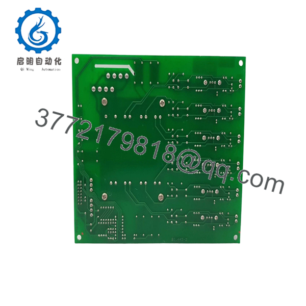
- 0P6267
- 0P6267
5. Installation & Configuration Guide
Stage 1: Pre-Installation Preparation (Estimated: 10 minutes)
⚠️ Safety First: Notify operations of downtime. Verify safe process condition. Apply lockout/tagout. Remove all UPS input power and wait 5 minutes minimum for capacitor discharge.
Tools Required
- ESD wrist strap
- PH1 screwdriver
- Fluke 115 multimeter
- Wire labels
- Smartphone for photos
- Flashlight
- ESD work surface
Data Backup
- Export UPS configuration if supported
- Photograph all cable locations
- Record board revision labels
- Capture jumper settings
- Record communication parameters
Older UPS cabinets frequently contain undocumented modifications. Assume nothing.
Stage 2: Removing the Old Module (Estimated: 5–10 minutes)
- Open cabinet cover
- Label all connectors
- Disconnect cable assemblies carefully
- Release board retainers
- Pull the PCB straight outward
⚠️ Never twist the board during removal.
I once saw a technician flex a board during extraction and crack a connector solder joint. Startup looked normal. Four hours later communication faults started appearing.
Inspect for:
- Dust buildup
- Burn marks
- Oxidation
- Cracked solder joints
- Connector wear
⚠️ Keep the removed board available until startup validation completes.
Stage 3: Installing the New Module (Estimated: 10 minutes)
- Wear ESD protection
- Verify 0P6267 model numbers match exactly
- Configuration Clone (Critical): Match all jumpers and switch settings
- Insert board carefully
- Lock hardware
- Reconnect wiring
Self-Checklist
[ ] Jumpers match
[ ] Wiring secure
[ ] Connectors seated
[ ] Retainers locked
This is the most common rookie mistake, but it happens constantly.
Take pictures before removal.
I can’t stress this enough.
Stage 4: Power-On & Testing (Estimated: 10–15 minutes)
Pre-Power Check
Use a multimeter to verify no short exists on control power rails.
Startup Sequence
- Energize cabinet only
- Observe LED startup sequence
- Verify alarm status
- Connect engineering software if available
- Confirm communication
- Test signal paths
- Restore field loads after validation
⚠️ Troubleshooting Note:
Solid fault indications immediately after installation often point toward:
- Incorrect board revision
- Connector placement errors
- Jumper mismatch
- Firmware compatibility problems
Technical Pitfall & Survival Guide
❗ Firmware Revision Mismatch
I’ve seen projects burn two days chasing communication faults.
Nothing was physically broken.
Firmware revision shifted and communication behavior changed slightly.
Document firmware before removal and request revision ranges when ordering.
❗ DIP Switch / Jumper Configuration
This is the most common rookie mistake.
Take a picture before pulling hardware.
Match:
- Node settings
- Jumpers
- Address values
- Termination selections
❗ Terminal and Connector Differences
Even visually similar GUTOR boards can have different connector arrangements.
Always check manuals.
Do not wire from memory.
❗ Power Draw Assumptions
Replacement hardware revisions can alter current demand.
Calculate total cabinet loading and maintain 20% power margin.
❗ ESD Damage
I once watched an engineer handle a board during winter without grounding.
Powered it up.
Immediate smoke.
Thousands of dollars disappeared instantly.
Wear the strap.
Keep these checks in mind and you’ll save yourself 90% of typical rework time.
SOP Quality Transparency
1. Inbound Inspection & Traceability
- OEM packaging review
- Serial traceability checks
- Anti-counterfeit verification
- Corrosion inspection
- UV yellowing inspection
- Accessory audit
2. Live Functional Testing
Testing performed on representative UPS hardware when available:
- Startup sequence verification
- Communication handshake checks
- Simulated operation
- Continuous runtime >24 hr
- Thermal monitoring
- Test report generation
3. Electrical Parameter Testing
- 500 V Megger insulation test >10 MΩ
- Ground continuity verification
- Hipot testing where applicable
4. Firmware & Configuration Verification
- Revision documentation
- Jumper photos
- Configuration archive
5. Final QC & Packaging
- QC signoff
- ESD bagging
- Bubble protection
- Heavy-duty packaging
- QC labeling with date
Test photos and videos are available upon request.
6. Frequently Asked Questions (FAQ)
Q1. Can I hot-swap GUTOR 0P6267?
No.
Do not attempt it.
This board operates inside UPS control architecture. Removing it under power risks connector damage and unpredictable startup faults.
Power down first.
Q2. Is GUTOR 0P6267 obsolete?
Most visible inventory appears through surplus channels rather than active OEM catalogs, which usually indicates a legacy product lifecycle. Plan replacement schedules carefully and verify stock before shutdown windows.
Q3. Is this genuinely new?
Ask directly:
- Factory Sealed
- New Original
- New Surplus
- Refurbished (tested)
Those labels describe different risk levels.
Public listings currently show both new and used inventory.
Q4. Will removing the board erase programming?
Usually not.
ISODRIVER boards generally perform hardware interface functions rather than storing operational logic.
Still back up everything before maintenance starts.
I’ve learned that lesson at 2:00 AM.
Q5. Why is pricing lower than OEM channels?
Most available inventory comes from surplus stock, decommissioned systems, or excess project inventory rather than active production streams.
Q6. What should I verify first after startup faults?
Start here:
- Board revision
- Jumper positions
- Connector placement
- Firmware compatibility
- Seating and retention hardware
Skip these checks and you can lose half a shift troubleshooting a five-minute installation mistake.



