
 WhatsApp: +86 16626708626
 Email:
  Phone: +86 16626708626
Description
3. Key Technical Specifications
| Parameter | Value |
| Logic Supply Voltage | 24 V DC |
| Output Type | High-current isolated gate drive signals |
| Circuit Protection | Over-current and short-circuit monitoring |
| Isolation | High-voltage galvanic isolation |
| Interface | Multi-pin ribbon cable and terminal block connectors |
| Operating Temperature | -10 to +55 °C |
| Storage Temperature | -25 to +70 °C |
| Relative Humidity | 5 to 95% (Non-condensing) |
4. Product Introduction & Supply Chain Strategy
The GUTOR 0P6281A is a specialized gate driver and inverter control module responsible for the precise switching of power semiconductors in industrial UPS systems. By converting low-voltage logic signals into high-energy pulses, it dictates the quality of the AC output delivered to critical plant loads. This board is typically found in Gutor’s heavy-duty PXP and PEW series, which serve as the backbone for power reliability in global offshore and refinery operations.
As an obsolete component, the 0P6281A represents a major single point of failure in older UPS architectures. Relying on refurbished drivers is exceptionally risky; a failed gate drive can cause a cascading failure of the IGBT or SCR power blocks, leading to massive repair bills and extended downtime. Securing “New Surplus” inventory ensures that the gate timing and isolation properties meet original factory tolerances, providing a 100% reliable insurance policy against semiconductor failure.
5. Installation & Configuration Guide
1.Pre-Installation (Prep & Safety):20 min.
Isolate the UPS and confirm that all DC bus capacitors are fully discharged. Use a multimeter to verify zero voltage at the inverter terminals. Wear a grounded ESD wrist strap to protect the logic circuits on the 0P6281A.
2.Removal:10 min.
Disconnect the control ribbon cables and the high-current gate leads. Mark each wire to ensure correct polarity during reinstallation. Unbolt the module from its standoffs, taking care not to stress the PCB.
3.Installation (Clone & Seat):15 min.
Verify that any jumpers or trimming potentiometers on the New Surplus 0P6281A match the original board settings. Mount the board securely and reconnect all leads, ensuring tight, low-resistance connections on the gate drive outputs.
4.Power-On & Testing:30 min.
Energize only the logic power first (Control Voltage). Verify that the diagnostic LEDs are in the “Ready” state. Use an oscilloscope to check the PWM gate pulses (if possible) before applying high-voltage DC to the inverter section.
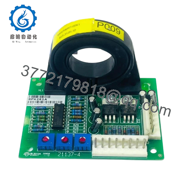
- 0P6281A
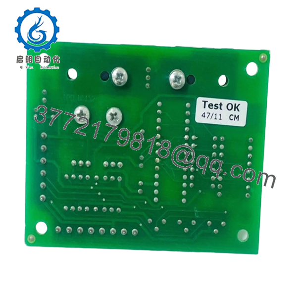
- 0P6281A
6. Firmware/Software Versions & Upgrade Notes
- Hardware Revision: The “A” suffix in 0P6281A denotes a specific hardware revision level. Ensure your system does not require a later “B” or “C” revision which might have different isolation ratings.
- Firmware Dependencies: While this is primarily an analog/logic driver board, it must synchronize with the main CPU (e.g., 0P2556B). Ensure the main controller firmware supports the switching frequencies calibrated on this specific gate driver.
- Warning: Never mix different revisions of gate drivers within a three-phase system; timing mismatches between phases can cause significant harmonic distortion or bridge short-circuits.
7. Frequently Asked Questions (FAQ)
Does this board include the power transistors (IGBTs)?
No. The 0P6281A is the control board that drives the transistors. It is sold as a separate logic module.
Why shouldn’t I just repair my old 0P6281A board?
The 0P6281A uses high-speed optocouplers and capacitors that degrade over 10-15 years of continuous heat exposure. Patching a failed board often leads to “infant mortality” failure of the repaired components or a failure elsewhere on the board shortly after. New Surplus is the only way to reset the reliability clock.
Can I use this in a 50Hz or 60Hz system?
Yes, the 0P6281A is designed to follow the switching frequency dictated by the UPS main controller, making it compatible with both 50Hz and 60Hz PXP/PEW configurations.
Is it safe to store this board for a long time?
Yes, if kept in its original ESD packaging in a climate-controlled room. We recommend a “Last-Time-Buy” strategy for this part, as New Surplus availability is dwindling globally.
What is the lead time for this part?
Since this is a stocked item in our New Surplus inventory, we typically ship within 24-48 hours. This is significantly faster than the 12-20 week lead times often quoted for legacy support from the OEM.



