WhatsApp: +86 16626708626
 Email:
 Phone: +86 16626708626
Description
Core Product Summary (Brand / Model / Key Attributes)
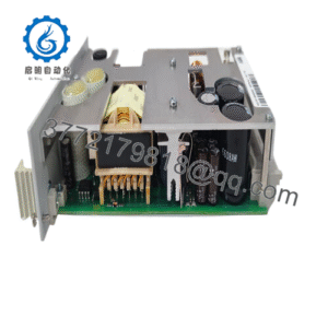
The GUTOR 21358-2 is an industrial-grade printed circuit board (PCB) subassembly engineered for integration within specialized GUTOR uninterruptible power supply (UPS) and industrial power conversion systems. Built to handle continuous electrical service requirements, this electronic module serves as a dedicated internal control, regulation, or interface subassembly designed to maintain operational stability within compatible GUTOR power management architectures.
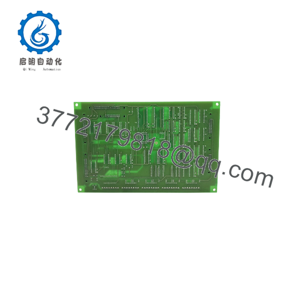
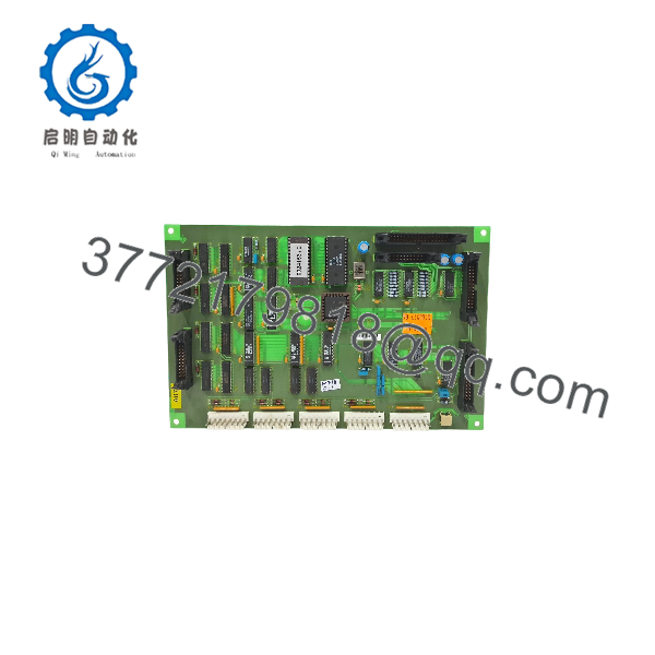
Constructed with high-reliability electronic components and multi-layer layout circuitry, the unit features standardized board-edge connection points and mounting configurations designed for seamless integration into designated equipment slots or backplanes. It operates within precise electrical parameters dictated by heavy-duty industrial power environments, requiring professional handling procedures and adherence to system-level integration guidelines during deployment and maintenance cycles.
Key Technical Specifications
| Specification Category | Technical Detail |
|---|---|
| Manufacturer / Brand | GUTOR |
| Model / Order Number | 21358-2 |
| Reference / Drawing Identifier | DPD 9349 |
| Product Type | Printed Circuit Board (PCB) / Electronic Subassembly |
| Primary Application | Industrial Power Systems / UPS Control Infrastructure |
| Approximate Weight | 0.280 kg (280 g) |
| Mounting Format | Internal Rack / Chassis Subassembly Integration |
Detailed Product Overview
The GUTOR 21358-2 functions as an internal electronic subassembly within complex industrial power distribution and conversion frameworks. In continuous industrial processes, internal control and interface boards are essential for processing logic signals, supervising subsystem responses, and ensuring synchronous operation across power electronic nodes. This printed circuit board is manufactured to meet rigorous industrial thresholds, ensuring dependable signal transmission and operational durability over extended duty cycles.
Integration of this subassembly requires strict adherence to system compatibility checks, controlled installation protocols, and careful mechanical alignment. Because the module handles sensitive internal control logic and signal routing, proper seating, reliable connector interface engagement, and compliance with standard electrostatic discharge (ESD) precautions are vital during handling, replacement, and routine maintenance workflows.
21358-2
21358-2
Engineering Selection Highlights
- Exact Model Match: Designated specifically under part number 21358-2, ensuring direct mechanical and functional replacement compatibility within targeted system architectures.
- Dedicated Subassembly Role: Acts as an internal printed circuit board tailored for specific processing, routing, or interface tasks within supported GUTOR equipment.
- Industrial Electronics Layout: Constructed with heavy-duty printed circuit board materials and component spacing optimized for standard industrial operating environments.
- Lightweight Profile: Features an approximate weight of 0.280 kg, structured for straightforward handling and integration into designated equipment slots.
- System Maintenance Support: Serves as a vital replacement component for upkeep, repair, and lifecycle maintenance of established industrial power management installations.
System Compatibility & Integration Requirements
| Item / Dependency | Verified Compatibility or Requirement | Practical Note |
|---|---|---|
| System Family | GUTOR Industrial Power and UPS Systems | Verify system model series and exact hardware revision numbers prior to installation. |
| Mounting Interface | Dedicated Subassembly Slot / Rack | Ensure precise physical guidance and secure locking into the designated backplane or chassis position. |
| Connection Protocol | Internal Board-Level Harness / Edge Connectors | Verify that all matching plugs and internal communication links are firmly engaged. |
Dimensions, Mounting & Connection Notes
- Physical Weight: Approximately 0.280 kg, formatted for internal card-rack installation.
- Mounting Configuration: Designed to slide into designated card guides, racks, or internal chassis slots within compatible GUTOR enclosures.
- Handling Precautions: Standard electrostatic discharge (ESD) safe handling practices, including grounded wrist straps and anti-static workstations, must be observed when handling the bare board.
- Environmental Limits: Must be deployed inside clean, climate-controlled industrial enclosures shielded from excessive moisture, dust, and corrosive vapors.
- Connection Integrity: Inspect edge connectors and interface pins for cleanliness and proper alignment before final seating.
FAQ
What is the GUTOR 21358-2?
The GUTOR 21358-2 is an industrial printed circuit board (PCB) subassembly utilized within specialized GUTOR power and UPS control equipment.
Which system environment does it support?
It is designed for integration into established GUTOR industrial power management, conversion, and uninterruptible power supply architecture setups.
What precautions are necessary during installation?
Technicians must observe standard electrostatic discharge (ESD) precautions, ensure correct physical alignment, and verify that all internal connectors are securely seated.
Can this board be used as a direct replacement part?
Yes, matching the exact order number (21358-2) ensures proper physical and functional integration as a subassembly replacement in compatible units.
Verification & Troubleshooting Notes
- Visual Inspection: Check the printed circuit board for any evidence of mechanical stress, damaged traces, or loose components prior to deployment.
- Interface Verification: Confirm that interface cables and backplane pins are completely free of debris or oxidation to prevent communication or power transmission errors.
- System Diagnostics: Monitor system-level status LEDs and controller error logs after installation to verify normal functional handshaking and operational readiness.