WhatsApp: +86 16626708626
 Email:
 Phone: +86 16626708626
Description
Core Product Summary (Brand / Model / Key Attributes)
The Gutor 0P1922 is a specialized printed circuit board assembly engineered by Gutor Electronic (a brand of Schneider Electric) to serve as a parallel operation controller within industrial uninterruptible power supply (UPS) systems and modular DC power platforms. Often cross-referenced in spare parts lists under variant designation 0P1922A, assembly location code A024, and bare-board identifier 640-4054, it coordinates load sharing, synchronization, and inter-unit communication across parallel-connected power systems.
Built for integration into Gutor industrial power cabinets—including PEW, PDW, and Mxx series architectures—the board slides into designated control slots within the internal rack assembly. By managing phase synchronization and load distribution logic between redundant or parallel UPS units, the controller supports continuous, fault-tolerant power delivery in critical infrastructure environments such as power generation plants, oil and gas facilities, and heavy industrial automation installations.
Key Technical Specifications
| Technical Parameter | Verified Specification |
| Manufacturer | Gutor Electronic (Schneider Electric) |
| Model / Order Number | 0P1922 (related variant designation: 0P1922A) |
| Associated Board / Location Codes | PCB 640-4054 / Assembly Location A024 |
| Product Type | Parallel Operation Controller Printed Circuit Board Assembly (PCA) |
| Primary Function | Synchronization, load sharing, and parallel operation control |
| System Compatibility | Gutor industrial UPS systems (PEW, PDW series) and Mxx modular DC platforms |
| Mounting Type | Internal cabinet rack slot / card cage installation |
Detailed Product Overview
The Gutor 0P1922 parallel operation controller board manages the coordination required when multiple Gutor UPS or power units operate together in parallel redundant or capacity-expanding configurations. In high-availability industrial power systems, parallel units must maintain precise output synchronization and balanced load sharing to prevent circulating currents or single-point overload trips. This printed circuit board assembly handles the control signaling and inter-cabinet communication logic necessary to keep parallel power modules aligned during normal operation and load transitions.
Engineered as an application-specific control card, the module installs into designated internal rack positions (typically referenced as A024 in Gutor spare parts documentation) within PEW, PDW, and Mxx series cabinets. When sourcing a replacement board, matching the primary order number (0P1922 or 0P1922A), the etched circuit board identifier (640-4054), and the existing board revision helps ensure compatibility with the host system’s backplane and control firmware.
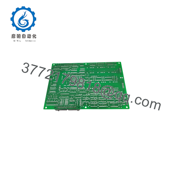
0P1922
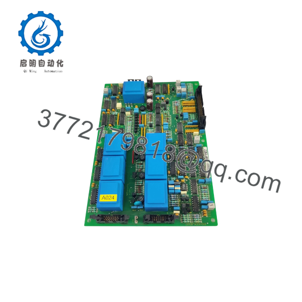
0P1922
Engineering Selection Highlights
- Parallel System Coordination: Dedicated specifically to synchronization and load-sharing control across parallel-connected Gutor power systems.
- Part Number & Board Cross-Check: Verify the primary code (
0P1922/0P1922A), PCB marking (640-4054), and hardware revision against the existing module to ensure exact hardware alignment. - Multi-Platform Compatibility: Documented in spare parts schedules for Gutor PEW and PDW industrial UPS lines as well as Mxx modular DC power platforms.
- Configuration Continuity: Replacement boards require matching any hardware jumper settings, DIP switches, or onboard firmware versions to the original installed unit before commissioning.
System Compatibility & Integration Requirements
| Item / Dependency | Verified Compatibility or Requirement | Practical Note |
| System Family | Gutor Industrial UPS (PEW / PDW Series) & Mxx DC Systems | Confirm exact system model and serial number against the unit’s spare parts list. |
| Part Number Cross-Reference | 0P1922 / 0P1922A / PCB 640-4054 | Verify suffix (A) and PCB revision level match the existing control rack configuration. |
| Rack Location | Designated internal control slot (e.g., A024) | Must be inserted into the specific parallel control slot defined in the cabinet wiring schematic. |
| Configuration & Firmware | Hardware jumpers / onboard firmware alignment | Record all jumper positions on the existing card and transfer settings prior to installation. |
Dimensions, Mounting & Connection Notes
- Form Factor: Plug-in printed circuit board assembly designed for internal card-rack or chassis mounting within Gutor power enclosures.
- Handling Precautions: Always wear a grounded electrostatic discharge (ESD) wrist strap when handling, inspecting, or installing the printed circuit board.
- Pre-Installation Configuration: Photograph and document all existing jumper settings, DIP switches, and ribbon cable connections on the original board before removal so they can be replicated accurately on the replacement unit.
- Connection Integrity: Align the board carefully within the rack card guides and apply even pressure until the edge connector is fully seated in the backplane.
FAQ
What is the Gutor 0P1922?
The Gutor 0P1922 is a parallel operation controller printed circuit board assembly manufactured by Gutor Electronic for industrial UPS and DC power systems.
What is the difference between 0P1922, 0P1922A, and 640-4054?
In Gutor spare parts documentation, 0P1922 and 0P1922A identify the parallel operation controller assembly, while 640-4054 is the bare printed circuit board reference number marked on the card.
Which Gutor systems use the 0P1922 controller?
It is documented for use in Gutor PEW and PDW series industrial UPS systems, as well as Gutor Mxx modular DC power platforms configured for parallel operation.
What does the parallel operation controller do?
It coordinates synchronization, load sharing, and control signaling between multiple Gutor power units operating in parallel.
Verification & Troubleshooting Notes
- Safe Isolation Before Replacement: Place the UPS system into Manual Bypass mode and isolate control power according to the cabinet’s OEM operating manual before removing or inserting the control board.
- Pre-Installation Inspection: Inspect the replacement board for physical damage, bent connector pins, or contamination, and verify that all jumper settings match the removed board.
- Post-Installation Verification: Restore logic power and confirm via the front operator display panel that normal status indicators illuminate and no parallel communication or synchronization alarms are active before transferring load back from bypass.