WhatsApp: +86 16626708626
 Email:
 Phone: +86 16626708626
Description
Core Product Summary (Brand / Model / Key Attributes)
The Gutor 0P3895AD is a main controller printed circuit board assembly (PCB ASSY XXW CONTROLLER) engineered by Gutor Electronic (Schneider Electric) for industrial uninterruptible power supply (UPS) systems. Identified in Gutor master parts lists under schematic reference designator A070 and associated with bare printed circuit board identifier 640-1371C, it serves as the central control processor for Gutor PxW / XXW series UPS architectures.
Documented in spare parts schedules for Gutor PEW series industrial UPS systems (such as the PEW 1005), the assembly manages core operational logic, power conversion supervision, and system control functions. Installed within dedicated internal control positions inside Gutor power cabinets, the 0P3895AD coordinates rectifier, inverter, and static bypass operations to support continuous power conditioning across critical industrial infrastructure in power generation, oil and gas, and heavy process facilities.
Key Technical Specifications
| Technical Parameter | Verified Specification |
| Manufacturer | Gutor Electronic (Schneider Electric) |
| Model / Order Number | 0P3895AD |
| Associated PCB / Reference Codes | PCB 640-1371C / Reference Designator A070 |
| Product Type | XXW Controller Printed Circuit Board Assembly (PCB ASSY XXW CONTROLLER) |
| Primary Function | Central UPS operational control and power conversion supervision |
| System Compatibility | Gutor PxW / XXW series industrial UPS systems (including PEW series, e.g., PEW 1005) |
| Mounting Type | Internal cabinet control rack / slot installation (A070) |
Detailed Product Overview
The Gutor 0P3895AD functions as the primary XXW controller printed circuit board assembly positioned at schematic location A070 within Gutor industrial UPS systems. In industrial power conditioning equipment, the A070 main controller governs system state transitions, coordinates rectifier and inverter control loops, monitors fault conditions, and manages static bypass switching to maintain uninterrupted power to critical downstream loads.
Built on bare printed circuit board 640-1371C (also associated in Gutor controller upgrade kits with the Blackbird controller platform), the assembly is documented in master parts schedules alongside companion interface assemblies such as the A071 DC interface fuse board (0P2405A). Because Gutor configures main controller assemblies with system-specific firmware and parameters tailored to individual UPS cabinet ratings and project specifications, verifying the exact order number (0P3895AD), the etched PCB revision (640-1371C), and host cabinet firmware compatibility is essential during maintenance or spare-part replacement.
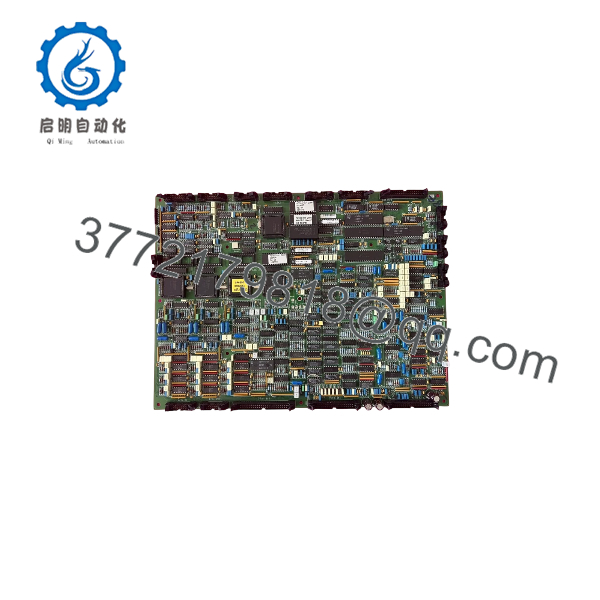
0P3895AD
Engineering Selection Highlights
- Primary UPS Control Role: Serves as the central XXW controller assembly at schematic location
A070within Gutor PxW / PEW series UPS cabinets. - Part Number & PCB Cross-Verification: Cross-check both the assembly order code (
0P3895AD) and the bare printed circuit board identifier (640-1371C) against the host cabinet’s master parts list to ensure exact hardware alignment. - Firmware & System Configuration Alignment: Gutor main controller boards operate with project-specific firmware and configuration parameters matched to the UPS cabinet serial number; confirm firmware version and software update requirements prior to installation.
- Companion Board Architecture: Interfaces directly within the control rack alongside companion
A071DC interface boards (such as0P2405Ain 220 VDC systems).
System Compatibility & Integration Requirements
| Item / Dependency | Verified Compatibility or Requirement | Practical Note |
| System Family | Gutor Industrial UPS Systems (PxW / PEW Series, e.g., PEW 1005) | Confirm exact match against the UPS cabinet serial number and OEM master parts list. |
| Part Number Cross-Reference | 0P3895AD / PCB 640-1371C | Verify PCB revision (Rev08, etc.) and populated components match the existing cabinet hardware. |
| Schematic / Slot Location | Reference Designator A070 | Install only in the designated main controller position specified in the cabinet wiring diagrams. |
| Firmware / Software Dependency | Project-specific UPS control firmware | Confirm firmware compatibility or required service-pack/software alignment with the host UPS configuration. |
Dimensions, Mounting & Connection Notes
- Form Factor: Printed circuit board assembly equipped with onboard processor heatsink, communication ports, and multi-pin interface connectors for internal cabinet installation.
- Handling Precautions: Always wear a grounded electrostatic discharge (ESD) wrist strap when unpacking, inspecting, or installing the printed circuit board assembly.
- Pre-Installation Documentation: Photograph and label all multi-pin ribbon cables, wire harnesses, DIP switches, and jumper positions on the existing board prior to removal so they can be replicated accurately on the replacement assembly.
- Connection Integrity: Align the board carefully within its designated
mounting guides or standoffs and verify that all connectors and retention hardware are clean and fully seated before restoring control power.
FAQ
What is the Gutor 0P3895AD?
The Gutor 0P3895AD is an XXW main controller printed circuit board assembly (PCB ASSY XXW CONTROLLER) manufactured by Gutor Electronic for industrial UPS systems.
What is the relationship between 0P3895AD, A070, and 640-1371C?
In Gutor documentation, 0P3895AD is the assembly order number, is the schematic reference designator for the main controller slot, and 640-1371C is the bare printed circuit board identifier marked on the card.
Which Gutor UPS systems use the 0P3895AD controller?
It is documented in Gutor master parts lists for PxW / PEW series industrial uninterruptible power supply systems, including models such as the PEW 1005.
What function does this controller board perform?
Positioned at schematic location , it serves as the central controller managing operational logic, power conversion supervision, and system control within the UPS cabinet.
Verification & Troubleshooting Notes
- Safe Isolation Before Servicing: Place the UPS into Manual Bypass mode and isolate all AC and DC power sources feeding the control electronics in accordance with the OEM cabinet operating manual before removing or installing the
controller board. - Pre-Installation Configuration Check: Compare the replacement
0P3895ADagainst the original assembly to verify identical PCB revision (640-1371C), jumper/DIP switch settings, and required firmware version for the specific UPS serial number. - Post-Installation Verification: Re-energize control power per the OEM startup sequence, verify that the operator display initializes without controller fault alarms, and confirm normal system status before transferring the load back from bypass.