
 WhatsApp: +86 16626708626
 Email:
  Phone: +86 16626708626
Description
Key Technical Specifications
| Parameter | TSR435S-5/15A |
|---|---|
| Manufacturer | Haltec |
| Model | TSR435S-5/15A |
| Product Type | Industrial power supply module |
| Input Voltage | 110 VAC / 230–240 VAC |
| Input Frequency | 47–63 Hz |
| Output Rating | 5 V / 15 A variant |
| Application | Industrial automation power supply |
| Series | TSR435S |
| Lifecycle Status | Discontinued |
| Replacement Consideration | Exact suffix and electrical ratings must be matched |
| Typical Procurement Status | Legacy / limited availability |
| Approx. Listed Weight | 1.08 lb |
The published TSR435S-5/15A listing identifies it specifically as a power supply module with 110/230–240 VAC input and 47–63 Hz frequency. The same source marks the model as discontinued by the manufacturer.
Important: Haltec also produced TSR435S-24/15A, so “TSR435S” alone is not sufficient to establish electrical interchangeability. The 5/15A and 24/15A variants should not be treated as direct substitutes without checking the equipment’s required output voltage.
Product Introduction
The Haltec TSR435S-5/15A is a legacy industrial power supply module designed for equipment requiring an AC-fed DC power source. Available documentation identifies 110/230–240 VAC input and 47–63 Hz operation, with the -5/15A variant associated with a 5 V, 15 A output configuration.
For maintenance teams supporting older automation equipment, the main issue is not simply finding a physically similar power supply. Output voltage, current capacity, mounting arrangement, connector assignment, and the exact suffix must all match the installed system.
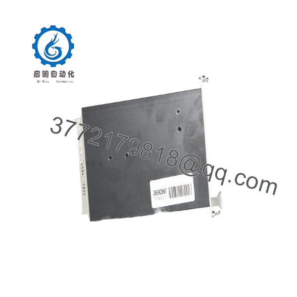
TSR435S-5/15A
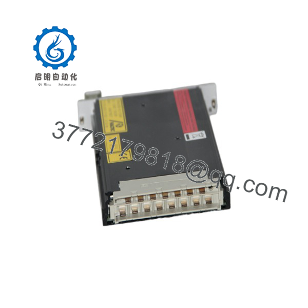
TSR435S-5/15A
Installation & Configuration Guide
Stage 1 — Pre-Installation Preparation | ~5 minutes
- Apply the site’s lockout/tagout procedure and isolate the AC supply.
- Confirm the replacement nameplate shows the correct .
- Record the existing input and output wiring.
- Photograph terminal positions before removing the original unit.
- Prepare an ESD strap, insulated screwdriver, multimeter, wire labels, and replacement hardware.
- Verify the required output voltage and current against the equipment documentation.
⚠️ Do not substitute a -24/15A for a -5/15A simply because the enclosure or model family looks similar.
Stage 2 — Remove the Existing Power Supply | ~5 minutes
- Confirm that the AC input is de-energized with a suitable meter.
- Label each conductor before disconnecting it.
- Disconnect AC input and DC output wiring.
- Remove the mechanical retaining hardware.
- Withdraw the module without stressing adjacent wiring.
- Inspect terminals, connectors, and mounting surfaces for heat damage or corrosion.
Keep the original unit until the replacement has passed commissioning. It can provide useful evidence if a wiring or configuration discrepancy appears.
Stage 3 — Install the Replacement | ~5 minutes
- Verify the complete model number against the removed unit.
- Check the enclosure and terminals for physical damage.
- Install the module in the original mounting position.
- Reconnect wiring according to the documented terminal assignment.
- Tighten connections using the equipment manufacturer’s specified torque.
- Check that no conductor is loose or contacting an adjacent terminal.
- Confirm adequate ventilation around the power supply.
⚠️ Never determine DC output polarity from wire color alone. Use the original equipment drawings and verify with a meter.
Stage 4 — Power-On & Testing | ~10–15 minutes
- Perform a final wiring and polarity inspection.
- Check for unintended shorts before energizing.
- Energize the AC input with downstream loads controlled where practical.
- Measure the DC output voltage.
- Check output stability with the normal equipment load.
- Monitor for abnormal heating, odor, noise, or protective shutdown.
- Restore the automation system and verify connected equipment operation.
- Record the installed part number and replacement date in the maintenance history.
For a discontinued power supply, documenting the replacement unit’s serial number and tested output voltage is worthwhile. It gives the next maintenance technician a traceable baseline.
Frequently Asked Questions (FAQ)
Is the Haltec still manufactured?
Available industrial automation listings identify the -5/15A as discontinued by the manufacturer. This makes surplus, unused legacy stock, refurbished units, and repair services potential procurement routes.
What is the input voltage /15A?
The published specification identifies 110 VAC / 230–240 VAC input with a 47–63 Hz input frequency.
s /15A interchangeableSR435S-24/15A?
No—not without engineering verification. The two models belong to the same family but have different output configurations. The suffix is therefore electrically significant.
Can I replace the with a modern power supply?
Potentially, but this should be treated as an engineering substitution rather than a simple model-number replacement. Check output voltage/current, connector configuration, physical dimensions, grounding, input requirements, transient behavior, and the downstream equipment’s power requirements.
What should I verify when buying a used ?
At minimum, verify the complete model suffix, nameplate ratings, physical condition, terminal condition, and tested output voltage. For a discontinued supply, request test documentation where available rather than relying only on a visual inspection.
e /15A suitable for a 24 VDC control circuit?
No. The -5/15A designation corresponds to the 5 V output variant identified in available listings. A 24 V requirement would require a different configuration or an appropriately rated replacement supply. Do not infer compatibility from the family name alone.
What information should be included in an RFQ?
Provide the complete model and suffix, equipment manufacturer/model, required input voltage, output voltage/current, connector or terminal arrangement, quantity, required condition, and any nameplate photographs. For legacy equipment, this information can prevent an otherwise expensive electrical mismatch.



