
 WhatsApp: +86 16626708626
 Email:
  Phone: +86 16626708626
Description
Key Technical Specifications
- Manufacturer: HIMA
- Part Number: 984200004
- Known Designation: A1 DIG
- System Family: HIMA ELOP II
- Product Classification: Safety control unit / digital binary-input module
- Nominal Supply Voltage: 24 V DC
- Binary Input Capacity: 32 binary inputs
- Primary Function: Receives discrete safety and process-permissive signals for the HIMA safety system
- Typical Signal Sources: Emergency-stop contacts, pressure switches, level switches, limit switches, relay contacts, valve-position feedback, and safety permissives
- System Application: Safety instrumented system and critical-control logic
- Mounting Requirement: Verify exact ELOP II rack, slot location, connector type, and terminal/interface assembly
- Configuration Requirement: Confirm I/O channel assignment, input logic, line-monitoring method, test-pulse behavior, and safety application configuration
- Interchangeability: Do not substitute a generic HIMA or Planar4 digital-input module for an A1 DIG ELOP II unit
- Replacement Rule: Match 984200004, A1 DIG, installed rack architecture, wiring interface, and validated safety configuration
The most specific distributor record identifies HIMA 984200004 as an A1 DIG ELOP II control unit with 24 V DC operation and 32 binary inputs. Other online pages conflict by describing it as a 16-channel Planar4 module, FSC 95xx module, safety relay, or central module. Those generic claims should not be used for safety-system engineering or replacement decisions.
Product Introduction
The HIMA 984200004, designated A1 DIG in the ELOP II architecture, is a 24 V DC safety-related binary-input control unit. It receives discrete field signals used by the safety system for shutdown logic, permissives, interlocks, emergency-stop circuits, and monitored equipment status. A distributor record identifies the unit with 32 binary inputs.
This is application-specific safety hardware, not a general PLC digital-input card. A proper replacement requires exact confirmation of the ELOP II rack, terminal interface, channel assignment, safety logic, and proof-test procedure. The wrong module or an unvalidated configuration can create false trips, masked faults, or a dangerous loss of diagnostic coverage.
Troubleshooting Quick Reference
| Symptom | Possible Cause | Relevance to This Part | Quick Check Method | Recommendation |
|---|---|---|---|---|
| Multiple safety inputs indicate fault simultaneously | Lost 24 V DC field supply, common return failure, interface-board issue, module supply fault, cabinet wiring damage | ⚠️ Medium | Measure the approved 24 V DC field supply and return at the designated terminal interface; compare affected channels and inspect shared fuses | Check common supplies and field interface before replacing 984200004 |
| One emergency-stop or permissive input remains active | Open contact, broken cable, loose terminal, failed field relay, input-channel fault | ⚠️ Medium | Follow the approved bypass and permit process; measure field state at the designated input terminal and compare controller diagnostics | Inspect field contact and wiring before replacing the module |
| One safety input remains permanently energized | Shorted cable, welded relay contact, incorrect wiring, failed sensor, input-channel fault | ⚠️ Medium | Isolate the field loop under approved procedures, then measure the circuit at the terminal interface and compare with the safety logic state | Find and correct the field-circuit fault before replacing the module |
| Safety system shows a communication or module fault | Rack interface issue, module not seated, power loss, failed module, system diagnostic fault | ✅ High | Review ELOP II diagnostics, inspect module seating and connector condition, and verify documented supply rails at the rack | Confirm rack power and interface condition before replacement |
| Plant shutdown occurs after module replacement | Incorrect module variant, channel wiring mismatch, inverted logic, missing configuration validation, bypass left active | ✅ High | Stop and review safety logic, channel mapping, wiring photographs, and commissioning checklist before returning the system to service | Follow the approved management-of-change and validation procedure |
| Inputs chatter or flicker | Loose terminal, contact bounce, inadequate sensor supply, cable damage, electrical interference, improper debounce configuration | ❌ Usually Low | Trend the input in the diagnostic system, inspect terminal torque, and measure field voltage during the event | Correct field wiring and approved logic settings before replacing hardware |
| Module has no indication or rack does not recognize it | Missing rack power, incorrect slot, bad backplane contact, bent pin, failed module | ✅ High | Isolate the system correctly, inspect board guides and contacts, then verify supply at documented rack test points | Reseat the module; replace only after rack and contact checks pass |
| Fault repeats after installing a replacement | Shorted field circuit, incorrect terminal wiring, supply transient, uncorrected external defect | ✅ High | Inspect field-circuit insulation, relay-coil condition, cable routing, supply quality, and terminal interface | Identify root cause before powering a second replacement |
Field warning: Do not treat a safety-input fault as a routine I/O problem. The channel may represent an emergency stop, burner-management permissive, turbine trip, gas-detection alarm, pressure trip, or final-element feedback. Follow the site’s safety lifecycle procedure, bypass authorization process, and documented proof-test requirements before forcing, lifting, or simulating any signal.
❗ Do not confuse ELOP II with Planar4 or FSC modules: The available records include conflicting generic descriptions. The clearest part-specific source identifies 984200004 as A1 DIG ELOP II, 24 V DC, 32 binary inputs. Do not use Planar4 16-channel, FSC 95xx, or generic safety-relay specifications to select, wire, or test this unit.
❗ Document every channel before removal: Photograph the installed A1 DIG label, rack slot, terminal interfaces, wire numbers, jumpers, fuses, and diagnostic indicators. Export or print the current safety logic and I/O cross-reference. It is the most common rookie mistake, but it happens constantly. Take a picture before you touch anything. Seriously.
❗ Input polarity and line monitoring matter: Do not assume the field circuits are simple 24 V DC contacts. Safety systems may use energized-to-trip logic, de-energized-to-trip logic, line monitoring, test pulses, dual channels, or external relays. Use the approved cause-and-effect chart, loop drawing, and HIMA safety application documentation.
❗ A replacement requires validation: Replacing a safety input unit can affect diagnostic coverage, fault response, proof-test status, and documented safety integrity. Do not return the process to normal service until the affected channels are tested and signed off under the site’s approved functional-safety procedure.
❗ Check the field circuit before installing a second module: A grounded cable, shorted solenoid, damaged relay base, water-intruded junction box, or unstable 24 V DC supply can cause repeated faults. I have seen a crew install two replacement safety cards before discovering a crushed cable in a tray. Check the loop first.
❗ ESD is not optional: Use a grounded wrist strap, ESD-safe work surface, and antistatic packaging. Handle the unit by the housing and card edges. Static damage may not appear immediately but can create intermittent diagnostic faults after commissioning.
Keep these checks in mind and you will save yourself 90% of typical rework time. If the fault remains unclear, contact technical support with complete module-label photos, rack and terminal-interface photos, diagnostic logs, I/O cross-reference, field-loop measurements, and the relevant cause-and-effect chart.
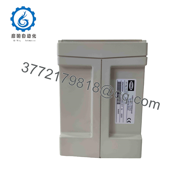
984200004
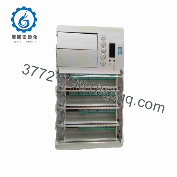
984200004
Frequently Asked Questions
What is HIMA 984200004?
HIMA 984200004 is identified as an A1 DIG ELOP II safety control unit with 24 V DC operation and 32 binary inputs. It is used to receive discrete signals in a HIMA safety-system application.
Is HIMA 984200004 a 16-channel Planar4 input module?
Do not assume that. A third-party listing describes 984200004 as a 16-channel Planar4 module, but that conflicts with the part-specific A1 DIG ELOP II record listing 32 binary inputs. Treat Planar4 compatibility, 16-channel count, SIL claims, temperature limits, and other generic specifications as unverified until confirmed through the installed HIMA documentation.
What field signals can the A1 DIG module monitor?
It typically receives binary field states used by safety logic, such as relay contacts, emergency-stop contacts, limit switches, pressure switches, level switches, valve-position feedback, and equipment permissives. The exact circuit design must be verified from the site loop drawings because safety inputs may use energized-to-trip logic, dual channels, line monitoring, test pulses, or external interposing relays.
Can I hot-swap the HIMA 984200004?
Do not assume hot swapping is permitted. This module belongs to a safety-system environment, and removal can create input faults, process trips, loss of diagnostics, or an unsafe bypass condition. Follow the approved HIMA maintenance procedure, safety lifecycle documentation, plant operating procedure, and permit/bypass authorization process.
Can I substitute another HIMA digital-input module?
No, not without an OEM-approved engineering review and a formal safety change process. A generic HIMA input module may have different channel count, voltage range, diagnostics, line-monitoring behavior, rack interface, safety certification scope, and application support. Match the exact 984200004 A1 DIG ELOP II identification first.
Will I lose safety logic when I replace the module?
The safety application may reside in a separate HIMA controller or programming environment, but field-channel assignments, diagnostics, proof-test status, and physical configuration can still be affected by a module replacement. Before removal, preserve the approved application backup, I/O cross-reference, cause-and-effect matrix, loop drawings, bypass status, and validation records.
Is HIMA 984200004 obsolete?
Treat it as a legacy HIMA ELOP II safety spare with limited availability. Current market records are primarily independent distributor or surplus listings rather than accessible OEM product documentation. Confirm actual stock, condition, hardware revision, test evidence, warranty, and return terms before issuing a purchase order.
Why is a New Surplus HIMA module less expensive than factory supply?
New Surplus stock can come from unused maintenance inventory, an uncommissioned project, a system modernization, or warehouse liquidation. It may be unused but not factory sealed. For safety hardware, lower cost is never the decision point by itself. Require clear traceability, actual-unit photos, visible serial and revision data, storage-condition evidence, functional testing, warranty coverage, and a documented return process.
What testing should a supplier perform before shipment?
For a HIMA 984200004 A1 DIG ELOP II safety-input unit, require a test record tied to the exact offered module:
- Verify the complete 984200004 and A1 DIG ELOP II identification, serial information, and hardware revision
- Photograph all labels, connectors, housing surfaces, rack interface, and terminal-interface connection points
- Inspect for corrosion, contamination, rework marks, cracked housing, bent contacts, damaged latches, and missing hardware
- Test only in a compatible HIMA ELOP II rack or documented equivalent fixture
- Apply controlled 24 V DC binary signals to the applicable input channels and verify correct state recognition
- Check channel diagnostics, common-supply behavior, and fault indication according to the applicable test procedure
- Confirm stable operation through an extended run while monitoring temperature and diagnostic status
- Record the test-rack identification, input method, channel coverage, test duration, observed diagnostics, and results
- Package in ESD-safe material with connector protection, foam support, QC sign-off, and written warranty terms
For safety-system hardware, “powers on” is not a functional test. The supplier should verify actual input recognition and diagnostic behavior on the correct platform. Test photos and videos should be available upon request.



