
 WhatsApp: +86 16626708626
 Email:
  Phone: +86 16626708626
Description
3. Key Technical Specifications
| Parameter | Specification / Value |
| System Compatibility | HIMA Planar F Subrack Assemblies |
| Circuit Architecture | Hard-wired solid-state components (No microprocessor) |
| Delay Technology | High-precision RC network with 5 configuration channels |
| Nominal Operating Voltage | 24 V DC |
| Voltage Supply Range | 20 to 30 V DC (including ripple) |
| Current Consumption | 45 mA at 24 V DC |
| Safety Certification | Suitable for up to AK 6 / SIL 3 architectures depending on loop wiring |
| Signal Input Levels | High: 15 to 30 V DC | Low: −3 to +5 V DC |
| Physical Dimensions | Standard 4U plug-in card configuration |
| Operating Temperature | 0 to +60°C |
4. Product Introduction & Supply Chain Strategy
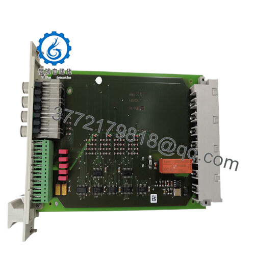
The HIMA F2106 is a hard-wired, safety-related multifunctional delay module belonging to the legacy Planar F system architecture. Operating independently of any central processing unit or internal software clock, this module relies on precise RC networks to execute critical time-dependent logic, such as delayed trip signals or valve travel constraints in emergency shutdown (ESD) loops. Because the module utilizes deterministic, discrete components, it is impervious to software hangs or firmware translation corruption, making it a reliable component in high-reliability chemical, petrochemical, and power generation processes.
From a Total Cost of Ownership (TCO) standpoint, securing a New Surplus F2106 card is an essential risk-management step for legacy installations. Because this line is discontinued by the OEM, finding active factory replacements is no longer a viable path. Refurbished or second-hand modules introduce severe vulnerabilities; age-related drift in legacy RC components can directly alter safety trip times, throwing off critical field timing windows. Maintaining factory-sealed new surplus inventory on-site safeguards your process from sudden, multi-day production losses caused by hardware exhaustion.

- F2106
5. Installation & Configuration Guide
Stage 1: Pre-Installation (Prep & Safety)
- Isolate Energy Sources: Verify that the power feeds to the Planar F subrack tier are switched off and locked out according to your local plant configuration parameters.
- Grounded Protection: Always wear a grounded ESD wrist strap attached to an unpainted metal surface on the enclosure chassis before pulling the card from its packaging.
- Inspect Rear Pins: Check the new F2106 card’s gold-plated edge connectors or blade pins for transportation damage or dust accumulation.
Stage 2: Removal
- Disengage Fasteners: Unscrew the upper and lower slot retaining screws mounting the faceplate to the subrack frame.
- Smooth Extraction: Use the integrated card pullers to free the old card from the backplane assembly. Pull straight outward along the structural guide rails to avoid torquing adjacent logic boards.
- Store for Diagnostics: Label and bag the extracted board immediately in an ESD-shielded container.
Stage 3: Installation (Clone & Seat)
- Configure Jumpers/Solder Points: If your facility utilizes hard-wired terminal assignments or specific component links on the board deck for time range selection, alter the configuration parameters of the new F2106 to mirror the old card exactly.
- Insert Smoothly: Slide the module deep into the designated slot tracking rails until you feel the rear connector pins fully mate with the subrack wiring harness.
- Lock Down: Fasten the front faceplate screws to secure proper grounding paths with the cabinet framework.
Stage 4: Power-On & Testing
- Re-Energize Subrack: Apply 24 V DC to the rack line and monitor current draws to catch unexpected ground faults early.
- Verify Delay Loops: Use a calibrated testing array to simulate the input trigger. Measure output response latency to confirm the module executes the delay within active process safety tolerances.
- Interlock Verification: Validate that downstream trip interlocks reset cleanly when the module completes its timing cycle.
6. Firmware/Software Versions & Upgrade Notes
Engineering Architecture Note: The HIMA F2106 belongs to a completely hard-wired, non-programmable electronic platform.
This hardware does not utilize code projects, operating systems, or programming interfaces like SILworX or ELOP II. There are no firmware registers to flashing or flash chips to maintain. System validation depends purely on physical wiring links, board revision numbers, and the precise values of the internal resistors and capacitors. When checking system engineering docs for a swap, focus entirely on matching the specific design index and suffix printed on the card layout sheet to ensure correct timing range compatibility.
7. Frequently Asked Questions (FAQ)
Q: Does this module require programming software or configuration updates?
A: No. The F2106 is an autonomous, hard-wired solid-state module. It operates strictly via discrete electronic timing pathways on the physical board layer, requiring no network handshakes, IP addressing, or code compilations.
Q: Why choose New Surplus inventory instead of an inexpensive refurbished F2106?
A: Refurbished analog timing cards pose risks because aging internal capacitors drift out of spec over time. A shift in capacitance changes the actual timing window of your safety loop. Buying a genuine New Surplus part ensures the components have zero service hours, matching the original factory tolerances.
Q: Can I hot-swap this card while the Planar F subrack is powered on?
A: No. Inserting or pulling a hard-wired analog card while the backplane is live can cause voltage spikes across adjacent signal tracks, potentially tripping unintended interlocks or damaging components on nearby logic cards. Always power down the local rack segment first.
Q: What do the different configuration channels on the module accomplish?
A: The RC 5 system architecture provides multiple independent delay pathways or ranges. These can be wired in series or parallel directly at the subrack terminal block to achieve specific timing combinations for your emergency shutdown sequences.
Q: How is this module tested before shipment if it lacks digital diagnostic registers?
A: Every F2106 module undergoes static signal injection and oscilloscope tracking in our testing loop. We measure input-to-output propagation latency across all channels under full load conditions to confirm the timing circuits perform reliably within original OEM specifications.



