
 WhatsApp: +86 16626708626
 Email:
  Phone: +86 16626708626
Description
Key Technical Specifications
| Parameter | Value |
|---|---|
| Model Number | F3 DIO 16/8 01 |
| Manufacturer | HIMA Paul Hildebrandt GmbH |
| Product Series | HIMatrix F3 |
| Product Type | Safety-related remote digital I/O device |
| Safety Application | HIMax and HIMatrix safety-system I/O expansion |
| Digital Inputs | 16 configurable digital inputs with line control |
| Digital Outputs | 8 safety-related two-pole digital outputs |
| Pulsed Outputs | 2 pulsed outputs |
| Output Architecture | Two series-connected switches per output; one switches L+ and one switches L− |
| Network Interface | Two-port 100BASE-TX Ethernet switch |
| Safety Protocol | SafeEthernet |
| Electrical Supply | 24 V DC nominal |
| Safety Integrity | Up to SIL 3 per IEC 61508, IEC 61511, and IEC 62061 |
| Machinery Safety Rating | Category 4 and Performance Level e |
| IEC 61131 Compliance | IEC 61131-2 I/O characteristics; IEC 61131-3 programming at controller level |
| Engineering Software | SILworX variant or ELOP II Factory variant; verify exact ordering version |
| User Program Execution | Not supported; remote I/O does not run a user program |
| Controller Connection | HIMax or HIMatrix controller via SafeEthernet |
| Multi-Master Capability | Not supported |
| Enclosure | Metal housing |
| Installation Area | Suitable for Zone 2 installation when installed to the manufacturer’s requirements |
| Dimensions, W × H × D | 205 × 114 × 88 mm |
| Approximate Weight | 1.3 kg |
| Operating Temperature | −25 to +60 °C |
| Storage Temperature | −40 to +85 °C |
| Humidity | 5–95%, non-condensing |
The HIMA F3 DIO 16/8 01 is a remote I/O device, not a standalone safety PLC or logic solver. It extends a compatible HIMax or HIMatrix safety controller through SafeEthernet and cannot execute a user application independently. Confirm the installed engineering environment—SILworX or ELOP II Factory—and the existing system version before purchasing a replacement.
Product Introduction
The HIMA F3 DIO 16/8 01 is a HIMatrix safety-related remote I/O module for distributed emergency shutdown, burner management, turbine protection, machine safeguarding, and process shutdown systems. It provides 16 configurable digital inputs, eight two-pole safety digital outputs, and two pulsed outputs for connection to a HIMax or HIMatrix safety controller through SafeEthernet.
This unit is selected where the application requires field-level I/O with SIL 3 capability and diagnostic coverage beyond standard PLC I/O. Its two-port 100BASE-TX SafeEthernet interface supports network wiring through the module, while its two-pole outputs switch both L+ and L− to help achieve a defined safe state.
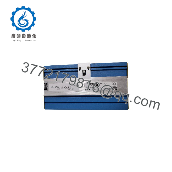
F3 DIO 16/8 01
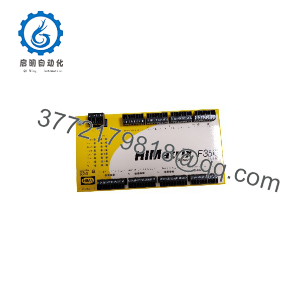
F3 DIO 16/8 01
Troubleshooting Quick Reference
| Symptom | Possible Cause | Relevance to This Part | Quick Check Method | Recommendation |
|---|---|---|---|---|
| No module status LEDs after power-up | Missing 24 V DC supply, blown cabinet fuse, incorrect polarity, loose terminal block, failed power distribution | ❌ Low until power is proven | Measure the 24 V DC supply directly at the module power terminals; verify polarity, cabinet fuse condition, and 0 V reference | Check supply wiring and fuses before replacing the F3 DIO 16/8 01 |
| Module has power but does not appear in SILworX | SafeEthernet cable fault, incorrect network configuration, duplicate IP or device settings, controller offline | ❌ Usually network or configuration related | Check both RJ-45 ports, link/activity LEDs, managed-switch diagnostics, and controller communication diagnostics in SILworX | Test with a known-good Ethernet patch cable and confirm the configured device identity before replacing hardware |
| SafeEthernet communication fault | Ring or line topology issue, damaged cable, bad connector, duplicate configuration, incompatible project download | ❌ Medium | Inspect both network paths, verify link LEDs, compare actual topology to the validated safety project, and review controller diagnostic logs | Correct network wiring and configuration first; do not bypass safety communications to keep a process running |
| One digital input stays ON | Field sensor energized, input wiring shorted to L+, line-control configuration mismatch, input-channel fault | ❌ Usually field-side | Remove the field wire at the designated terminal and observe the input state in SILworX; measure voltage at the input terminal to 0 V | If the signal remains active with field wiring removed and a known-good test setup, investigate module input-channel failure |
| One digital input stays OFF | Open field circuit, failed sensor, missing 24 V DC, damaged cable, wrong input configuration | ❌ Usually field-side | Measure the sensor output and 24 V DC supply; temporarily simulate the input only under approved maintenance and safety procedures | Repair field wiring or sensor first; verify the configured line-control method matches the circuit design |
| Safety output does not energize | Safety logic demand not satisfied, external interlock active, missing load supply, output diagnostics fault, wiring open | ❌ Low until logic is checked | Review the controller safety logic and diagnostic buffer; measure supply and output voltage at the output terminal under a permitted test condition | Do not replace the I/O blindly; identify which permissive, trip, or interlock is blocking the output |
| Safety output does not de-energize | Incorrect safety application logic, forced output, welded external relay or contactor, wiring feedback path | ❌ Usually not the module | Remove power only under approved lockout/tagout procedures; check whether voltage disappears at the F3 DIO output and whether the final element remains energized | If the module output drops but the field device stays energized, inspect the external relay, contactor, interposing circuitry, and feedback wiring |
| Multiple inputs and outputs fault together | Lost 24 V field supply, common return fault, terminal connector issue, water ingress, electrical noise | ❌ Usually external power or wiring | Check common supply terminals and return conductors; inspect terminal blocks for heat damage, loose screws, corrosion, and moisture | Repair power distribution and wiring before considering a module replacement |
| Module fault occurs after replacement | Wrong project, wrong firmware compatibility, device identity mismatch, old configuration not restored | ✅ Medium | Record the original unit’s firmware and configuration before removal; compare project diagnostics and the replacement device’s identification in SILworX | Request a replacement within the required firmware range and load only the approved, validated safety application |
| Intermittent I/O or network faults | Cabinet vibration, poor grounding, damaged shield termination, excessive temperature, loose connectors | ✅ Medium | Inspect mounting, grounding, Ethernet connectors, cabinet temperature, and field-cable shielding; trend diagnostics over time | Correct mechanical and installation issues first; replace the module only if the failure follows it in a controlled test |
| Output circuit reports fault after field-device replacement | Incorrect load type, reversed polarity, short circuit, wrong external protection, changed wiring | ❌ Low | Compare the actual field wiring to the approved loop drawing; verify load current and protective devices | Do not wire from memory. Restore the approved circuit before resetting safety diagnostics |
❗ Firmware and project warning: Record the existing controller project version, F3 DIO 16/8 01 device identity, firmware information, and diagnostic history before removing the old module. I have seen a technician swap a healthy remote I/O device, load an outdated project, and create a SafeEthernet configuration fault that held a production unit offline for two days. The physical replacement was fine; the validated safety project was not.
❗ Output wiring warning: The eight outputs are two-pole safety outputs. They use two switches in series, with one switching L+ and the other L−. Do not assume they behave like a standard single-sided 24 V DC PLC transistor output. Verify the loop drawing, load supply, return path, and feedback circuit before connecting field wires.
❗ ESD and functional-safety warning: Isolate power under the site’s approved lockout/tagout procedure, use a grounded ESD wrist strap, and never use a forced I/O condition as a production workaround. Safety I/O replacement must follow the site’s functional-safety management process, including proof-test requirements and post-change validation.
If you are stuck, contact technical support with front and terminal-side photos, the SILworX or ELOP II Factory diagnostic export, SafeEthernet topology, controller model, module firmware details, and measured 24 V DC values. Keep these checks in mind and you will save yourself most of the usual rework time.
Frequently Asked Questions
What is the HIMA F3 DIO 16/8 01 used for?
The F3 DIO 16/8 01 expands the field I/O capacity of a HIMax or HIMatrix functional-safety system. It reads 16 digital signals from emergency stops, limit switches, pressure switches, flame-system contacts, valve feedbacks, and similar devices. It also provides eight two-pole safety outputs for final elements such as interposing relays, shutdown solenoids, safety contactors, and annunciation circuits.
The module is commonly applied in emergency shutdown, process shutdown, burner management, turbine protection, and machine-safety systems where the complete safety function is designed for SIL 3 capability.
Is the F3 DIO 16/8 01 a standalone safety controller?
No. To be honest, this is an easy mistake to make because the module has its own metal enclosure, Ethernet ports, and substantial I/O count. It is a remote I/O device only. It does not execute a user program, is not multi-master capable, and must connect to a compatible HIMax or HIMatrix safety controller through SafeEthernet.
Does this module support standard Ethernet protocols such as Modbus TCP or EtherNet/IP?
Do not assume that it does. The F3 DIO 16/8 01 uses HIMA SafeEthernet for its safety-system communication path and includes two 100BASE-TX switch ports. It is not a general-purpose remote I/O block for Modbus TCP, EtherNet/IP, PROFINET, or EtherCAT integration. Verify the exact HIMA system architecture and approved communication design before ordering.
Can I hot-swap the HIMA F3 DIO 16/8 01?
Do not treat it as hot-swappable unless the approved HIMA documentation, validated safety application, and your site procedure explicitly permit that exact operation. This module participates in a safety function. Pulling it live can initiate a trip, generate a SafeEthernet fault, remove output power, or leave the process in an unsafe or unplanned state.
Use the site change-control process. Place the plant or machine in a safe condition, isolate power as required, record the existing wiring and diagnostics, install the replacement, and complete the prescribed functional test before returning to service.
Can I directly replace an F3 DIO 16/8 01 with any HIMA digital I/O module?
No. Match the exact model number, I/O count, safety-output structure, engineering software version, firmware compatibility, SafeEthernet configuration, terminal wiring, and validated application configuration. An 8-output module with a similar name may not provide the same two-pole output arrangement, diagnostics, or terminal assignment.
If the exact part is unavailable, obtain a written migration recommendation from HIMA or a qualified safety-system integrator. A safety I/O substitution is an engineered change, not a catalog cross-reference.
What should I document before removing the old module?
Take clear photographs of every terminal block, Ethernet connection, module label, status LED state, and cabinet location. Export the current controller diagnostics and validated project. Record the module’s firmware version, SafeEthernet topology, configured device identity, physical network port usage, connected field loop numbers, and 24 V DC supply measurements.
It sounds tedious until you are standing in front of a shutdown system at 3:00 AM. A five-minute photo record often prevents a day of rework.
Is the F3 DIO 16/8 01 obsolete, and how should I manage spare stock?
This is a legacy HIMatrix remote I/O part, and availability can be limited depending on the exact firmware, condition, and supply chain. Treat verified spare availability as a maintenance risk item. For critical safety systems, keep a controlled spare with documented storage conditions, verified firmware, test records, anti-static packaging, and a clear link to the approved safety-system configuration.
Do not install an unverified surplus unit directly into a critical safety loop without inspection and functional validation.
How should a New Surplus F3 DIO 16/8 01 be tested before shipment?
A credible test process starts with traceability and inspection: verify the manufacturer label, exact part number, serial number, factory seals, housing condition, terminals, RJ-45 ports, and absence of corrosion, rework marks, or damaged connector latches. Confirm accessories and original packaging where available.
Then power the module from a regulated 24 V DC source, verify the startup LED sequence, connect it to a genuine HIMatrix or HIMax SafeEthernet test environment, and check communication in the appropriate SILworX or ELOP II Factory configuration. Exercise all 16 digital inputs using controlled 24 V DC test signals and verify each of the eight two-pole outputs using suitable monitored loads. Run a sustained load test while monitoring temperature, diagnostics, and communications.
For final quality control, document the firmware version, capture configuration records, inspect grounding and terminals, package the unit in ESD-safe material, and provide test photos, video, and a formal test report on request. The module is specified for safety applications up to SIL 3 and has 16 configurable digital inputs, eight two-pole outputs, two pulsed outputs, and SafeEthernet connectivity.



