
 WhatsApp: +86 16626708626
 Email:
  Phone: +86 16626708626
Description
Key Technical Specifications
| Parameter | Specification |
| Safety Integrity Level | SIL 3 (IEC 61508 / IEC 61511) |
| Digital Inputs | 8 safety-related digital inputs (24 VDC, galvanically isolated) |
| Digital Outputs | 8 digital DO+ outputs (L- ground), 2 digital DO- outputs (S+ ground), 2 pulsed outputs |
| Switching Current | 0.5 A to 2 A per output channel (dependent on configuration) |
| Ethernet Interfaces | 2x RJ-45, 10BASE-T/100BASE-TX with integrated switch |
| Network Protocol | safeethernet (HIMax and HIMatrix controller connection) |
| Response Time | \ge 10 ms system response / Ethernet interface processing |
| Operating Voltage | 24 VDC (-15\% / +20\%) |
| Programming Environment | Configuration via SILworX or ELOP II Factory |
| Enclosure Type | Heavy-duty compact metal chassis |
| Operating Temperature | -20 ^\circC to +60 ^\circC |
Product Introduction & Supply Chain Strategy
The HIMA F3 DIO 8/8 01 is a safety-related remote I/O module designed to safely process digital signals within distributed emergency shutdown (ESD), burner management (BMS), and fire and gas protection architectures. Communicating seamlessly with HIMax and HIMatrix main controllers via safeethernet, it offloads field device wiring while maintaining certified SIL 3 integrity.
In high-consequence process plants, sourcing safety hardware as New Surplus is a non-negotiable risk management policy. Sourcing uncommissioned, factory-sealed modules ensures that internal optocouplers, diagnostic relays, and power regulation circuits have zero latent thermal degradation. This eliminates the severe financial and environmental risks associated with secondhand safety devices failing during a critical trip event.
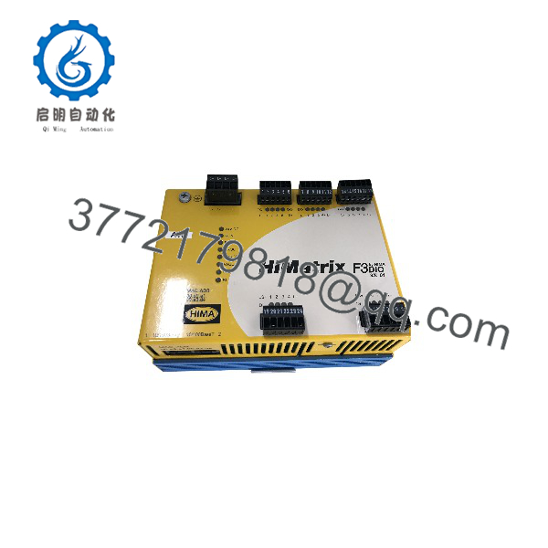
F3 DIO 8/8 01
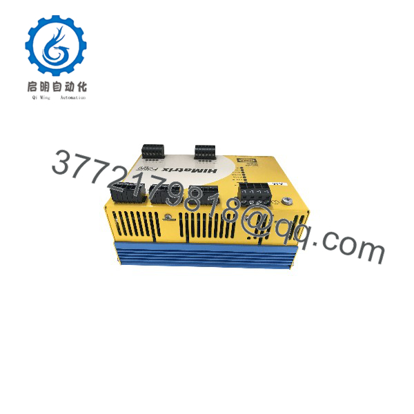
F3 DIO 8/8 01
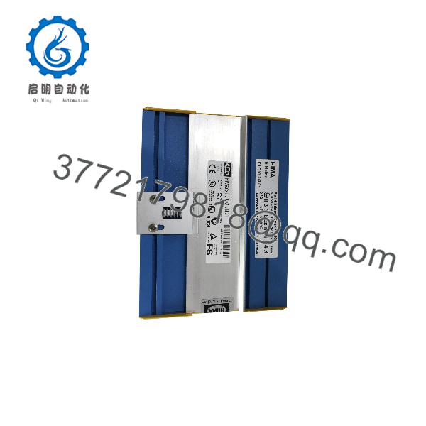
F3 DIO 8/8 01
Installation & Configuration Guide
Stage 1: Pre-Installation (Prep & Safety)
- Safety Isolation: Confirm the safety loop is placed in a bypassed or safe state according to plant safety protocol. De-energize the main 24 VDC feeder supplying the rack.
- Static Protection: Put on an ESD grounded wrist strap before handling the metal chassis or network patch cables.
- Configuration Capture: Document IP address assignments, MAC address labels, and safety rack ID DIP switch settings from the existing unit.
Stage 2: Removal
- Disconnect Field Wiring: Unplug removable terminal blocks or unscrew wiring harnesses attached to the digital input and output lines.
- Unplug Communications: Disconnect both RJ-45 safeethernet cables from ports 1 and 2.
- Unmount Chassis: Loosen the mounting fasteners or release the DIN-rail locking mechanism to remove the unit safely.
Stage 3: Installation (Clone & Seat)
- Physical Mounting: Secure the F3 DIO 8/8 01 to the mounting plate or DIN rail, establishing a low-impedance connection to protective earth (PE).
- Network Connection: Reconnect the safeethernet patch leads to the integrated dual-port Ethernet switch.
- Terminal Connection: Reattach field I/O terminal connectors, verifying that DO+ and DO- polarities match the safety loop drawings.
Stage 4: Power-On & Testing
- Voltage Verification: Verify that field supply voltage across terminal blocks measures a clean 24 VDC within tolerance.
- Power-On Self-Test: Energize the 24 VDC rail. Verify that the power LED illuminates green and internal self-diagnostic routines complete without triggering a system fault.
- Safeethernet Handshake: Confirm via SILworX or ELOP II Factory engineering tools that the connected safety controller establishes a verified safeethernet link with the module.
Firmware/Software Versions & Upgrade Notes
- Engineering Tools: The F3 DIO 8/8 01 exists in dedicated variant models engineered specifically for either SILworX or ELOP II Factory configuration environments. Ensure hardware variant compatibility before system integration.
- Network Protocol: Communication depends on safeethernet frame parameters; verify that system cycle time configuration meets or exceeds the required safety response time (\ge 10 ms).
- Hardware Replacement Warnings: Do not flash or mismatch system firmware without verifying safety system checksums. Replacing a SILworX-based module with an ELOP II-based unit will prevent safety handshakes and halt communication across the safeethernet segment.
Frequently Asked Questions (FAQ)
Q: Can the HIMA F3 DIO 8/8 01 operate as a standalone safety controller?
A: No. The F3 DIO 8/8 01 functions strictly as a safety-related remote I/O extension. It cannot execute user logic independently and must be linked to a HIMax or HIMatrix safety controller over safeethernet.
Q: Why should our plant buy New Surplus instead of lower-cost refurbished safety modules?
A: Refurbished safety equipment carries hidden risks, such as aged internal capacitors or degraded channel isolation optocouplers. Buying New Surplus ensures factory-fresh safety performance, original component tolerances, and total compliance with SIL 3 functional safety audit requirements.
Q: How does the safeethernet protocol handle channel faults on this module?
A: The module continuously conducts internal self-tests. If a short circuit, cross-wire fault, or internal component failure occurs, the unit safely de-energizes the affected outputs and transmits diagnostic fault frames back to the primary controller.
Q: Are the digital outputs configured for single-pole or two-pole switching?
A: The module includes 8 DO+ outputs (line-switching) and 2 DO- outputs (ground-switching). Channels DO4+, DO8+, DO4-, and DO8- can be paired to form fully isolated two-pole switching outputs for high-integrity actuator control.
Q: What installation precautions prevent static or power surges from damaging the unit?
A: Always establish a solid chassis ground to protective earth (PE) prior to wiring field signals. Ensure that all 24 VDC field power supplies maintain galvanic isolation and use surge protection devices on exposed long-distance field cable runs.
Q: What warranty and authenticity guarantees come with this module?
A: All New Surplus units are guaranteed 100% genuine HIMA product, complete with original serial tracking and a full 1-Year functional warranty. Every unit undergoes physical pin inspection and power-on diagnostic validation prior to dispatch.



