
 WhatsApp: +86 16626708626
 Email:
  Phone: +86 16626708626
Description
Key Technical Specifications
| Parameter | Value |
|---|---|
| Manufacturer | HIMA Paul Hildebrandt GmbH |
| Model | F3322 |
| Product Type | 16-channel digital output module |
| System Compatibility | HIMA H41q / H51q safety systems |
| Output Channels | 16 independent digital outputs |
| Output Voltage | 24 VDC nominal |
| Output Current | 500 mA per channel |
| Maximum Load | 12 W per channel |
| Load Type | Resistive, inductive, lamp loads |
| Short Circuit Protection | Yes |
| Current Limiting Threshold | >550 mA |
| Safety Isolation | Protective separation (ProtecS) |
| Fail-Safe Behavior | Outputs switch off when L- supply is interrupted |
| Power Consumption | 5 VDC: 110 mA; 24 VDC: 150 mA plus load current |
| Module Width | 4 TE |
| Maximum Modules per I/O Rack | 10 output modules with nominal load |
| Maximum Simultaneous Output Load | 8 A per I/O subrack |
| Recommended Fuse | 4 A slow-blow |
| Operating Temperature | -20 °C to +60 °C |
| Protection Rating | IP20 cabinet installation |
Product Introduction
The HIMA F3322 is a 16-channel digital output module designed for HIMA HIQuad H41q and H51q safety systems. It receives safety controller commands and switches 24 VDC field loads such as solenoid valves, relays, and alarm devices. Each output channel supports loads up to 500 mA (12 W) with integrated short-circuit current limitation.
The module is used in safety instrumented systems where controlled de-energization and output diagnostics are required. Before replacement, engineers should verify rack compatibility, output load calculations, field wiring, and safety application validation requirements.
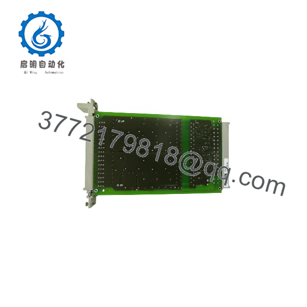
F3322
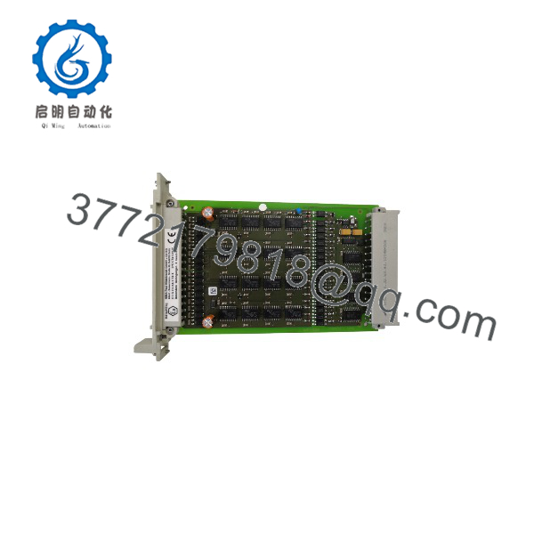
F3322
Installation & Configuration Guide
Stage 1: Pre-Installation Preparation (Approx. 15 minutes)
⚠️ Safety First
- Notify plant operations before working on the safety output system.
- Confirm connected actuators can be placed into a safe condition.
- Apply lockout/tagout procedures to the HIMA cabinet power supply.
- Wait at least 5 minutes for stored energy discharge.
- Verify zero voltage before touching field wiring.
Tools Required
- ESD wrist strap
- PH1 screwdriver
- Digital multimeter
- Wire labels
- Smartphone for wiring photos
- HIMA engineering workstation
Data Backup
Before removing the module:
- Save the current HIMA safety application configuration.
- Record:
- Rack number
- Slot position
- Module identification
- Hardware revision
- Photograph:
- Output terminal wiring
- Field actuator connections
- Module LED status
- Record connected load information:
- Solenoid valve current
- Relay coil ratings
- External protection devices
Stage 2: Removing the Old Module (Approx. 10 minutes)
- Remove cabinet covers if required.
- Label every output wire before disconnecting.
- Disconnect terminal blocks carefully.
- Release the module retaining screws.
- Pull the F3322 straight from the rack connector.
- Inspect:
- Backplane pins
- Connector condition
- Dust contamination
- Mechanical damage
⚠️ Note: Keep the original module until the replacement has passed functional testing. Old safety I/O modules provide important wiring and configuration references.
Stage 3: Installing the New Module (Approx. 15 minutes)
- Wear an ESD strap before handling the replacement unit.
- Verify:
- Model: HIMA F3322
- System: H41q / H51q
- Function: 16-channel digital output
⚠️ Configuration Clone — Critical Step
- Replicate the original configuration:
- Output channel assignment
- Field wiring arrangement
- Load grouping
- Safety logic mapping
- Insert the module into the correct I/O rack slot.
- Ensure the rear connector is fully seated.
- Tighten front locking screws.
- Reconnect field output wiring.
Self-Checklist
- Correct F3322 model verified
- Rack slot confirmed
- Output wiring matched
- Load current checked
- Module secured properly
Stage 4: Power-On & Testing (Approx. 20 minutes)
Pre-Power Check
- Measure 24 VDC field supply voltage.
- Verify output wiring polarity.
- Confirm load current does not exceed 500 mA per channel.
- Check for output short circuits.
Power-On Steps
- Energize the HIMA rack.
- Observe module LEDs.
- Connect HIMA engineering software.
- Verify:
- Module recognition
- Diagnostic status
- Safety controller communication
- Output channel status
- Perform output simulation tests.
- Confirm connected actuators respond correctly.
⚠️ Troubleshooting Note
- Output fault: Check field wiring and load current.
- Multiple output trips: Verify total rack load does not exceed 8 A.
- No output signal: Check L- supply because interruption forces outputs to the safe OFF state.
Frequently Asked Questions (FAQ)
Can the HIMA F3322 be hot-swapped under power?
Do not assume hot replacement is permitted. The is installed in a safety-related I/O rack, and replacement procedures depend on the HIMA system configuration and plant safety procedures. Remove power unless the approved maintenance procedure specifically allows live replacement.
What is the main function of the HIMA ?
The is a 16-channel digital output module that switches 24 VDC signals to field devices such as valves, relays, and indicators in HIMA safety systems. Each output channel supports up to 500 mA or 12 W loads.
Is the HIMA obsolete?
The belongs to the legacy HIMA HIQuad safety system family. Availability depends on remaining industrial inventory. Many plants maintain these modules as spare parts because replacing a certified safety system requires engineering review and validation.
Can the directly replace another HIMA output module?
Not always. HIMA output modules have different channel counts, safety functions, and electrical characteristics. Verify the exact part number, rack compatibility, and approved spare list before installation.
Will replacing the erase the safety program?
No. The safety application is stored in the HIMA controller configuration, not inside the output module. However, the replacement module must match the hardware configuration used by the safety application.
Why is a surplus priced differently from current safety modules?
Legacy safety hardware pricing depends on inventory condition, availability, testing records, and documentation. New Original / New Surplus units typically come from unused industrial stock, while refurbished units require functional verification before reuse.
What should I verify before ordering an HIMA ?
Check:
- HIMA system type: H41q / H51q
- Exact model:
- Output channel count
- Field load current
- Rack slot compatibility
- Safety application requirements
A similar-looking HIMA module may not provide the same output function.
How should a surplus module be tested before installation?
A proper inspection process should include:
- OEM label and serial number verification.
- Visual inspection for corrosion and connector damage.
- Installation test on a compatible HIMA rack.
- LED and diagnostic verification.
- Output simulation with controlled loads.
- Functional test report generation.
Test records and inspection photos should be retained for safety maintenance traceability.



