
 WhatsApp: +86 16626708626
 Email:
  Phone: +86 16626708626
Description
Key Technical Specifications
| Parameter | Value |
|---|---|
| Model Family | HIMatrix F35 |
| Manufacturer | HIMA Paul Hildebrandt GmbH |
| Product Type | Compact safety-related controller with integrated I/O |
| Safety Certification | Up to SIL 3 |
| Functional Safety Standards | IEC 61508, IEC 61511, IEC 62061 |
| Machinery Safety Rating | Category 4; Performance Level e |
| Digital Inputs | 24 safety-related digital inputs |
| Digital Outputs | 8 safety-related digital outputs |
| Analog Inputs | 8 safety-related analog inputs |
| Counter Inputs | 2 safety-related counters |
| Counter Frequency | Up to 100 kHz |
| Ethernet Switch Ports | 4 × RJ-45, 10/100 Mbit/s |
| Fieldbus Interfaces | Up to 3, variant-dependent |
| Safety Communication | SafeEthernet |
| Standard Communications | Variant-dependent; verify exact F35 order code and project |
| Supply Voltage | 24 V DC |
| Permitted Supply Range | 24 V DC, −15% to +20% |
| Digital-Output Current | Channels 1–3 and 5–7: 0.5 A at 60 °C; channels 4 and 8: 1 A at 60 °C or 2 A at 50 °C |
| Digital-Output Minimum Load | 2 mA per channel |
| Analog Input Range | Configurable 0–10 V DC or 0/4–20 mA, project-dependent |
| Analog Input Resolution | 12-bit nominal; 9-bit operating value |
| Operating Temperature | Standard version: 0 to +60 °C; F35 034 variant: −25 to +70 °C |
| Environmental Protection | IP20 |
| Mounting | Horizontal 35 mm DIN rail |
| Dimensions, W × H × D | Approximately 257 × 114 × 97 mm |
| Approximate Weight | 1.2 kg |
| Ex-Zone Capability | Approved variants suitable for Zone 2 installation |
| Engineering Platforms | SILworX or ELOP II Factory, version dependent |
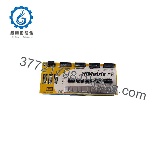
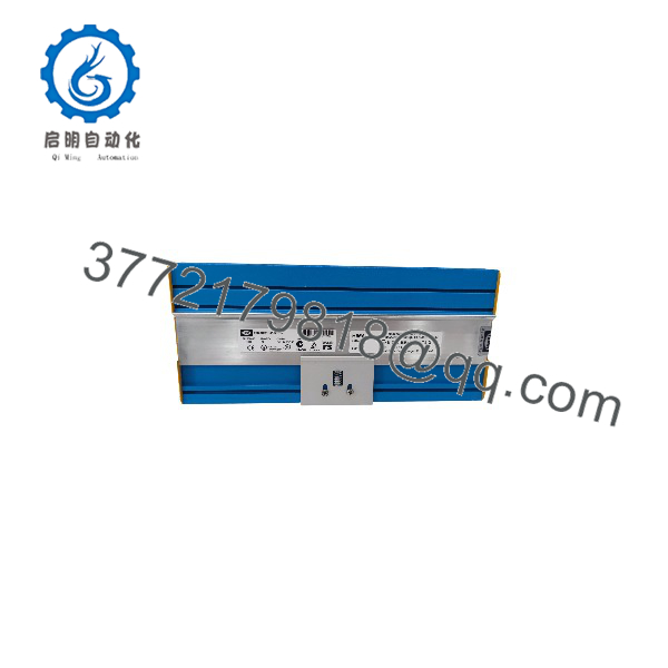
The HIMA HIMatrix F35 is a compact, standalone-capable safety controller—not a passive remote I/O block. It combines safety logic execution, 24 digital inputs, eight digital outputs, eight analog inputs, two high-speed counters, and Ethernet switching in one DIN-rail-mounted enclosure. The exact suffix matters: for example, HIMA identifies F35 034 as a coated, shock-resistant version rated for −25 to +70 °C.
Product Introduction
The HIMA HIMatrix F35 is a compact safety PLC for emergency shutdown, burner management, machinery safeguarding, turbine protection, and safety interlock applications. It integrates 24 safety digital inputs, eight safety digital outputs, eight analog inputs, two counters, and four Ethernet switch ports in a single 24 V DC DIN-rail controller.
The F35 is chosen when a safety function needs local logic, analog measurement, high-speed counter processing, and SafeEthernet connectivity without a separate CPU rack. It can support SIL 3 applications when configured, installed, validated, and maintained as part of the complete safety function. Verify the full F35 suffix, software platform, firmware, licensed protocols, and validated project before ordering.
F35
F35
Troubleshooting Quick Reference
| Symptom | Possible Cause | Relevance to This Part | Quick Check Method | Recommendation |
|---|---|---|---|---|
| No LEDs or controller does not boot | Missing 24 V DC supply, reversed polarity, blown external fuse, loose terminals, failed supply | ❌ Low until input power is proven | Measure 20.4–28.8 V DC directly at the F35 supply terminals using a calibrated meter; inspect polarity, 0 V reference, PE arrangement, and upstream fuse | Restore a correct 24 V DC supply before replacing the controller |
| Power LED is on but controller does not enter RUN | Safety application fault, corrupted project, configuration mismatch, firmware mismatch, hardware self-test failure | ✅ Medium to high | Connect with the approved SILworX or ELOP II Factory environment; read diagnostic buffer, controller state, and project compatibility information | Export diagnostics before any change. Use the validated project and match firmware before replacing hardware |
| Controller remains in STOP or safe state | Emergency-stop input active, safety permissive missing, input discrepancy, communication watchdog active, field-device fault | ❌ Usually field logic or field wiring | Review the online safety logic and diagnostic messages; identify the first failed permissive rather than only the final trip output | Correct the initiating safety condition. Do not bypass inputs or force outputs to return equipment to service |
| One digital input is permanently ON | Short to L+, failed sensor, cross fault, line-monitoring configuration error, input channel fault | ❌ Usually field-side | Remove the field conductor under approved procedures and observe the input in online diagnostics; measure terminal voltage to 0 V | If the state remains ON after the wire is removed, prove the input channel using a controlled test source |
| One digital input remains OFF | Open circuit, missing sensor supply, failed contact, incorrect input threshold, wiring break | ❌ Usually field-side | Measure voltage at the F35 input terminal; compare the signal with configured thresholds and test the field device | Repair field wiring or sensor first; verify the project input configuration matches the actual circuit |
| Multiple digital inputs fail together | Common sensor supply loss, terminal block issue, shared return fault, cabinet wiring damage | ❌ Low | Check the relevant 24 V sensor supply and common return; inspect terminal screws, fuse groups, and marshaling terminals | Repair shared field power or wiring before considering controller replacement |
| One safety output will not energize | Safety logic not permissive, output overcurrent, external load short, missing load supply, channel fault | ❌ Low until logic is checked | Read the controller’s output diagnostics; measure voltage at the F35 output and the field load under an approved test condition | Identify whether logic blocks the output. If the output is commanded but faulted with a known-good load, investigate the channel |
| Safety output stays energized when it should drop | Incorrect application logic, forced output, external relay/contact welded, feedback wiring error | ❌ Usually external final element | Under approved lockout/tagout, determine whether the F35 output voltage drops. If it drops but the device remains energized, inspect the relay, contactor, solenoid, and feedback circuit | Do not replace the controller unless its output remains energized contrary to the verified safety command |
| Analog input reads 0 or out of range | Open 4–20 mA loop, sensor supply failure, incorrect 0–10 V versus current configuration, broken signal wire | ❌ Usually field configuration | Measure actual loop current in series or voltage at the input terminal; compare hardware wiring and project channel type | Correct wiring and scaling first. Confirm the configured analog range before replacing the F35 |
| Analog signal is noisy or unstable | Improper shield grounding, common-mode noise, poor 24 V supply, loose terminals, bad transmitter | ❌ Usually external | Compare the F35 measurement with a calibrated loop meter; inspect shield termination and verify single-point grounding unless the design specifies otherwise | Correct field installation issues before changing the controller |
| Counter value is missing or incorrect | Wrong 5 V/24 V counter wiring, A/B/C phase issue, frequency above limits, encoder supply fault | ❌ Usually field-side | Verify encoder voltage, channel wiring, phase relationship, and measured frequency; confirm the application does not exceed 100 kHz | Correct encoder setup and validate counting direction before replacing hardware |
| Ethernet link LED off | Broken cable, failed switch port, wrong topology, remote device unpowered | ❌ Usually network-related | Use a known-good Cat5e/6 cable, verify remote switch power, inspect RJ-45 latches, and test another F35 port | Replace the cable first. If a known-good link works on another port but not the suspected port, document a possible port fault |
| SafeEthernet communication fault | Incorrect network configuration, duplicate settings, wrong project, cable fault, topology error | ❌ Usually engineering or network issue | Compare physical topology to the approved safety design; inspect SafeEthernet diagnostics and controller project settings | Restore the validated network configuration. Never bypass safety communications as a production workaround |
| Replacement F35 cannot accept project | Wrong F35 variant, SILworX versus ELOP II Factory mismatch, incompatible firmware, licensing mismatch | ✅ High | Compare the original controller order code, firmware, engineering platform, project version, and option configuration before installation | Request an exact compatible replacement and load only the approved, validated project |
| Repeated faults after hot cabinet operation | Ambient temperature exceeded, blocked ventilation slots, loose DIN rail mounting, internal aging | ✅ Medium | Measure enclosure temperature, confirm 20 mm horizontal and 100 mm vertical clearance, and inspect ventilation openings | Improve cooling and mounting conditions. Use the correct temperature-rated F35 variant where required |
❗ Variant warning: “F35” is a product family, not a complete order code. HIMA publishes multiple versions for SILworX and ELOP II Factory. F35 034, for example, is the coated, shock-resistant, −25 to +70 °C variant. Do not assume that an F35 03, F35 031, F35 034, or another suffix will accept the same project or meet the same environmental requirement.
❗ Firmware warning: Before pulling the existing controller, capture its full nameplate, serial number, firmware version, licensing data, project version, and diagnostic history. I have seen a replacement controller hold a plant shutdown because the hardware was correct but the site tried to load a SILworX project into an ELOP II Factory variant. That is not a field wiring problem. It is a compatibility problem.
❗ Output-load warning: Do not treat all eight outputs as equal. Channels 1–3 and 5–7 are rated at 0.5 A at 60 °C; channels 4 and 8 allow 1 A at 60 °C and up to 2 A at 50 °C. Check output loading, inrush current, flyback suppression, and cabinet temperature before declaring a channel failed.
❗ ESD and safety warning: Isolate the 24 V DC control supply under the approved lockout/tagout procedure. Wear a grounded ESD wrist strap. Any replacement must be followed by documented functional testing of each affected safety loop, including final elements and feedbacks. Do not use software forces or jumper wires as a substitute for a validated safety-function test.
If diagnostics remain unclear, contact technical support with front and terminal-side photos, full F35 suffix, firmware and software-platform details, controller diagnostic export, project compatibility message, network topology, and measured 24 V DC values. Keep these checks in mind and you will save yourself most of the usual rework time.
Frequently Asked Questions
What is the HIMA HIMatrix F35?
The HIMatrix F35 is a compact safety-related controller with integrated I/O and Ethernet switching. It is used to execute safety logic while reading field inputs and controlling shutdown outputs. Standard F35 hardware includes 24 digital inputs, eight digital outputs, eight analog inputs, two counters, and four 10/100 Mbit/s Ethernet switch ports.
Is the F35 a standalone safety PLC or only a remote I/O module?
It is a standalone-capable safety controller. Unlike an F3 DIO remote I/O module, the F35 executes the safety application itself. It can be deployed locally for a machine or process unit, or as part of a distributed HIMatrix safety architecture using SafeEthernet.
What safety rating does the F35 support?
The F35 controller has TÜV certification for use in safety-related applications up to SIL 3 under IEC 61508, IEC 61511, and IEC 62061. It is also associated with Category 4 and Performance Level e machinery-safety applications. The installed system only achieves those levels when the entire loop—including sensors, wiring, logic, final elements, diagnostics, proof testing, and application validation—meets the documented design requirements.
Can I hot-swap a HIMatrix F35 controller?
No. Treat it as a live safety logic solver. Removing power or disconnecting it can initiate a safe shutdown, interrupt SafeEthernet communications, de-energize outputs, and stop the protected machine or process. Isolate the power only after placing the process in an approved safe condition and following site lockout/tagout and functional-safety change-control procedures.
The replacement process should include a current project backup, configuration and firmware comparison, documented wiring photos, controlled installation, startup diagnostic review, and a post-change functional test.
Will the existing safety program remain after I replace the F35?
Do not count on it. Program and configuration retention depend on the F35 version, engineering platform, firmware compatibility, licensing, and commissioning procedure. Before replacement, export and protect the approved project from SILworX or ELOP II Factory, record controller identity and firmware, and ensure the replacement accepts the same validated project.
After restoring the application, prove every changed or affected safety function. A controller that shows RUN does not prove that an emergency stop, shutdown valve, burner trip, or overspeed loop is working correctly.
Can I use any F35 variant as a direct replacement?
No. Match the complete part number and environmental version, not just “F35.” Verify digital and analog I/O count, counter requirements, fieldbus option, Ethernet configuration, installed protocols, SILworX versus ELOP II Factory platform, firmware, temperature range, coating, shock rating, hazardous-area approval, and project compatibility.
If the original unit is an F35 034, a basic F35 may not provide the same −25 to +70 °C range, protective coating, or IEC 61373 Class 1B shock qualification.
Is the HIMatrix F35 obsolete?
HIMA’s online downloads list older F35 manuals as discontinued, while the HIMatrix product family remains described by HIMA as a compact safety-system range. Exact lifecycle status depends on the complete F35 variant and regional support program. For installed legacy systems, source verified replacement stock and maintain the validated engineering tools, software licenses, project archives, spare connectors, and documented firmware requirements.
How should a New Surplus HIMA F35 be tested before shipment?
Start with traceability and physical inspection: verify the full F35 order code, serial number, security labels, terminal blocks, Ethernet ports, DIN-rail latch, housing, conformal-coating condition where applicable, and absence of corrosion, bent terminals, rework marks, or damaged seals.
For functional testing, install the controller in an approved HIMatrix test environment with a regulated 24 V DC SELV/PELV supply. Verify normal power-up and self-test indication, establish communication using the correct SILworX or ELOP II Factory platform, and confirm the precise firmware and hardware identity. Use controlled 24 V DC test signals for all 24 digital inputs, load-test all eight outputs within their channel ratings, inject known analog 0–10 V and 4–20 mA values into all eight analog inputs, and exercise both counter channels with a calibrated signal source up to the required test frequency.
Run the controller under load for more than 24 hours while monitoring diagnostics, temperature, Ethernet communications, and unexpected resets. Document the test rack, firmware, input/output results, current draw, diagnostic export, and final QC sign-off. Package the controller in ESD-safe material with protected terminals and heavy-duty outer packaging. Test photos and video should be available upon request. HIMA documents the F35 as a 24 V DC safety controller with 24 digital inputs, eight digital outputs, eight analog inputs, two counters, and safety capability up to SIL 3.



