
 WhatsApp: +86 16626708626
 Email:
  Phone: +86 16626708626
Description
Key Technical Specifications
| Parameter | Value |
|---|---|
| Manufacturer | HIMA Paul Hildebrandt GmbH |
| Model | F60 MI 24 01 |
| Product Family | HIMatrix F60 |
| Module Type | Safety-related mixed input module |
| Input Channels | 24 channels |
| Input Configuration | Individually configurable per channel |
| Analog Input Signal | 0/4–20 mA current input |
| Digital Input Function | Proximity switches, safety switches, resistor-wired contacts |
| Digital Input Standard | EN 60947-5-6 compatible proximity switches |
| Safety Integrity Level | SIL 3 according to IEC 61508 / IEC 61511 / IEC 62061 |
| Performance Level | PL e according to EN ISO 13849-1 |
| Safety Category | Category 4 applications |
| Installation Position | HIMatrix F60 subrack slots 3–8 |
| Power Supply | 24 VDC system supply through F60 rack |
| Configuration Software | SILworX or ELOP II Factory depending on firmware generation |
| Communication Interface | Internal F60 backplane communication |
| Operating Temperature | Verify exact rating from current HIMA system documentation |
| Mounting Type | Plug-in rack module |
| Approximate Weight | 0.35 kg |
Product Introduction
The HIMA F60 MI 24 01 is a mixed input module for the HIMatrix F60 safety controller platform. It provides 24 configurable input channels that can operate as analog current inputs (0/4–20 mA) or digital safety inputs for field devices such as proximity switches and monitored contacts.
This module is used in safety-related automation systems where signal acquisition must comply with IEC 61508 and related functional safety requirements. Engineers replacing an existing unit should verify firmware compatibility, SIL configuration, channel parameters, and F60 rack addressing before commissioning.
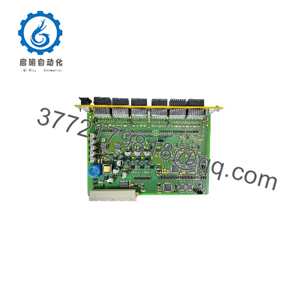
F60 MI 24 01
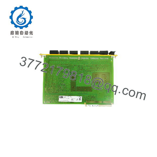
F60 MI 24 01
Installation & Configuration Guide
Stage 1: Pre-Installation Preparation (Approx. 15 minutes)
⚠️ Safety First
- Notify operations and confirm the safety system can enter a controlled maintenance state.
- Verify the protected process is in a safe condition.
- Apply lockout/tagout procedures to the F60 cabinet power supply.
- Wait at least 5 minutes before handling the module.
- Confirm no residual voltage exists before disconnecting field wiring.
Tools Required
- ESD wrist strap
- PH1 screwdriver
- Digital multimeter
- Wire labels
- Smartphone for wiring documentation
- HIMA engineering workstation with SILworX or ELOP II Factory
Data Backup
Before removing the module:
- Upload and save the current safety application configuration.
- Record the F60 rack slot location.
- Document:
- Channel configuration
- AI/DI assignment
- Input scaling parameters
- Error monitoring settings
- Photograph terminal wiring and module identification labels.
Stage 2: Removing the Old Module (Approx. 10 minutes)
- Remove the front terminal connectors from the module.
- Label every field wire before disconnecting.
- Release the upper and lower locking screws.
- Pull the module straight along the rack guide rails.
- Remove the module carefully from the backplane connector.
⚠️ Note: Keep the original MI 24 01 module until the replacement has completed safety validation. The old module provides a reference for wiring and configuration.
Stage 3: Installing the New Module (Approx. 15 minutes)
- Wear an ESD strap before handling the replacement module.
- Verify:
- Model: HIMA F60 MI 24 01
- System: HIMatrix F60
- Input Type: Analog 0/4–20 mA or digital input configuration
⚠️ Configuration Clone — Critical Step
- Match the original channel configuration exactly.
Check:
- Channel AI/DI assignment
- Signal range
- Short-circuit/open-circuit monitoring
- Safety parameter settings
- Insert the module into the correct F60 slot.
- Press the front plate until the module fully engages with the backplane connector.
- Tighten upper and lower fixing screws.
- Reconnect field terminals.
Self-Checklist
- Correct F60 slot confirmed
- Wiring labels matched
- AI/DI configuration verified
- Module locked into rack
- Terminal connections secured
Stage 4: Power-On & Testing (Approx. 20 minutes)
Pre-Power Check
- Verify 24 VDC supply condition.
- Check field wiring polarity.
- Confirm no short circuit exists between input terminals.
Power-On Steps
- Energize the HIMatrix F60 rack.
- Check front LEDs.
- Connect engineering software.
- Verify:
- Module identification
- Firmware compatibility
- Channel diagnostics
- Safety application configuration
- Test input signals using calibrated simulation equipment.
- Confirm safety logic response.
⚠️ Troubleshooting Note
- Red fault indication: Check module diagnostics and channel error codes.
- Incorrect analog values: Verify 0/4–20 mA scaling and transmitter wiring.
- Communication issue: Check F60 rack configuration and firmware compatibility.
Frequently Asked Questions (FAQ)
Can the HIMA F60 MI 24 01 be hot-swapped under power?
No. The MI 24 01 is a safety-related I/O module installed in the HIMatrix F60 rack. Remove power before disconnecting the module. Hot removal can create unexpected safety system behavior and may damage rack connections.
Is the HIMA F60 MI 24 01 obsolete?
The HIMatrix F60 platform is a legacy safety controller family, and MI 24 01 availability depends on remaining industrial inventory. Replacement units are commonly sourced as New Original, New Surplus, or tested refurbished stock. Always verify exact hardware revision before installation.
Can the MI 24 01 use analog and digital inputs at the same time?
No. Each channel can be configured for analog or digital operation, but analog and digital input functions cannot be used simultaneously on the same channel configuration.
Which engineering software is required for configuration?
The required tool depends on the HIMA operating system version. Older systems use ELOP II Factory, while newer firmware generations use SILworX. Confirm the CPU operating system version before commissioning.
Will replacing the MI 24 01 erase the safety program?
No. The safety application resides in the F60 CPU module, not inside the MI 24 01 input module. However, the replacement module configuration must match the original hardware setup before returning the system to service.
What should I verify before purchasing an F60 MI 24 01 replacement?
Confirm:
- HIMatrix F60 compatibility
- Exact model: MI 24 01
- Hardware revision
- Required channel configuration
- SIL application requirements
- Terminal wiring arrangement
A similar-looking HIMA input module may not have the same safety functions or channel characteristics.
How should a surplus MI 24 01 module be tested before installation?
A proper incoming inspection should include:
- Verify OEM label and serial number.
- Inspect enclosure condition and connector pins.
- Test installation on a compatible HIMatrix F60 rack.
- Verify LED operation and diagnostics.
- Simulate analog and digital inputs.
- Generate a functional test record.
Test photos and inspection documentation should be available upon request for traceability.



