
 WhatsApp: +86 16626708626
 Email:
  Phone: +86 16626708626
Description
Key Technical Specifications
| Parameter | Value |
|---|---|
| Model Number | F7126 |
| HIMA Order Code | 990000111 |
| Manufacturer | HIMA Paul Hildebrandt GmbH |
| Product Family | PES H51q / HIQuad legacy safety system |
| Product Type | Isolated DC/DC rack power supply module |
| Primary Function | Converts 24 V DC input to regulated 5 V DC system power |
| Nominal Input Voltage | 24 V DC |
| Permitted Input Range | 24 V DC, −15% to +20% |
| Input Ripple Limit | Less than 15% peak-to-peak |
| Output Voltage | 5 V DC ±0.5 V, continuously adjustable |
| Factory Output Setting | 5.4 V DC ±0.025 V |
| Rated Output Current | 10 A |
| Current Limiting | Approximately 13 A |
| Overvoltage Protection | Approximately 6.5 V DC ±0.5 V |
| Output Short-Circuit Protection | Yes |
| Input-to-Output Isolation | Safe electrical isolation |
| Efficiency | At least 77% |
| Primary Fuse | 6.3 A slow-blow |
| Front-Panel Adjustment | Test socket and output-voltage adjustment potentiometer |
| Redundant Supply Requirement | Output-voltage difference ≤0.025 V between supplies |
| EMC Classification | Limit Class B per VDE 0871/0877 |
| Module Width | 8 SU / 8 TE |
| Mounting Location | Compatible H51q/HIQuad rack power-supply position |
| Approximate Dimensions | 210 × 130 × 30 mm |
| Approximate Weight | 0.6 kg |
| Lifecycle Status | Legacy / limited spare availability |
The HIMA F7126 is a 24 V DC-to-5 V DC DC/DC converter for the H51q rack, not a 220 V AC power supply, not an analog-output module, and not a standalone 24 V field supply. The module provides isolated 5 V DC system power with up to 10 A capacity and supports controlled redundancy when the two supply outputs are matched within 0.025 V.
Product Introduction
The HIMA F7126, order code 990000111, is an isolated DC/DC power supply module for legacy PES H51q and HIQuad safety-system racks. It converts a 24 V DC cabinet supply into the regulated 5 V DC rail used by the controller and I/O architecture, delivering up to 10 A of output current.
The F7126 is selected as an exact spare for H51q installations where rack power continuity matters. It includes adjustable output voltage, current limiting, overvoltage protection, short-circuit protection, and safe input-to-output isolation. Verify the installed rack type, exact order code, input wiring, redundancy arrangement, and output-voltage setting before replacement.
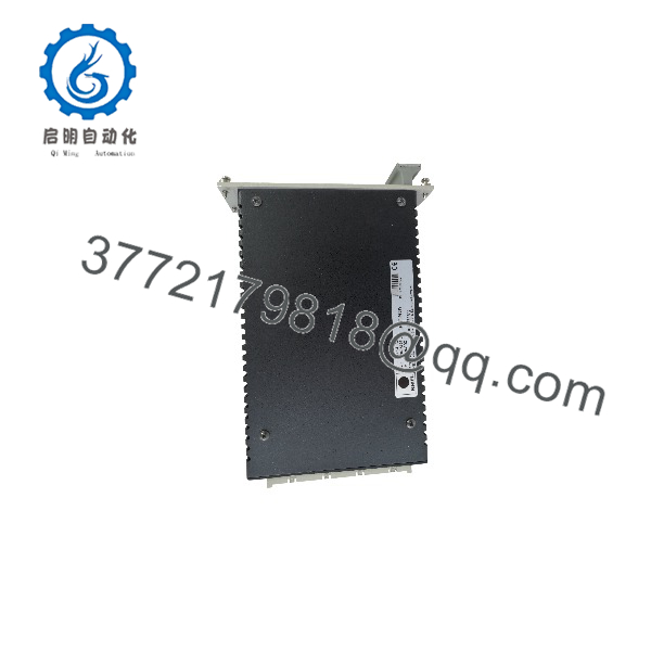
F7126
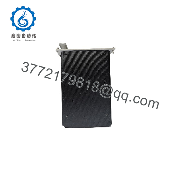
F7126
Troubleshooting Quick Reference
| Symptom | Possible Cause | Relevance to This Part | Quick Check Method | Recommendation |
|---|---|---|---|---|
| H51q rack has no CPU or I/O indications | Missing 24 V DC feed, tripped cabinet fuse, incorrect polarity, loose input terminals, failed F7126 | ❌ Low until input is proven | Measure 20.4–28.8 V DC directly at the F7126 input terminals using a calibrated meter such as a Fluke 115; inspect upstream 24 V DC supply, fuse, and common return | Restore supply and correct wiring before replacing the power module |
| 24 V DC input is correct but rack remains dead | internal fault, output fuse issue, backplane connection fault, output voltage set incorrectly | ✅ High | Measure the 5 V DC rail at the designated test point or rack test location; compare to the required setting and inspect module seating | If 24 V DC is correct and 5 V DC output is absent, replace or bench-test the |
| Rack resets intermittently | 24 V supply sag, loose wiring, overloaded 5 V rail, output voltage adjustment drift, high cabinet temperature | ✅ Medium | Trend 24 V input and 5 V output during peak system activity; inspect diagnostics, terminal torque, ventilation, and total rack loading | Correct input instability or overload first. Replace the only if a stable test setup confirms output dropout |
| Output is low, such as below 4.5 V DC | Excessive load, shorted I/O/CPU module, output setting drift, supply fault | ✅ Medium | Measure 5 V DC at the test point under load; remove nonessential modules only under an approved procedure and observe whether output recovers | Find the overloaded or shorted rack module before condemning the power supply |
| Output is above allowed rack voltage | Incorrect potentiometer adjustment, failed regulation circuit, incorrect redundant supply tracking | ✅ Critical | Measure output with a calibrated meter at the test socket; compare with the factory 5.4 V DC ±0.025 V setting and site documentation | Do not operate the rack with overvoltage. Isolate it and correct the setting or replace the |
| Primary fuse blows on energization | Input wiring short, reversed polarity, failed internal converter, downstream rack short, incorrect fuse type | ✅ Medium | Isolate the and inspect input wiring; confirm the installed fuse is 6.3 A slow-blow; reconnect loads incrementally under approved procedure | Do not increase fuse size. Identify whether the fault follows the PSU or the rack load |
| becomes hot or smells burnt | Excessive output current, blocked ventilation, high ambient temperature, internal component aging | ✅ High | Measure 5 V DC load current if the system design permits; inspect airflow and cabinet temperature; check for discoloration with power isolated | Remove overload and improve cooling. Replace any heat-damaged module |
| Two redundant supplies show load-sharing instability | Output voltages not matched, one supply aging, incorrect redundancy wiring, unequal cable resistance | ✅ High | Measure each supply output at its test socket with the same calibrated meter; compare readings | Adjust or replace so the voltage difference does not exceed 0.025 V; verify the rack redundancy wiring |
| One redundant supply carries all load | Output voltage of the second supply set too low, input missing, fuse open, wiring resistance imbalance | ❌ Usually adjustment or wiring | Confirm 24 V DC input to both modules; measure both 5 V outputs; inspect fuses and output connections | Restore input and match outputs before replacing either supply |
| New replacement causes rack alarms immediately | Output setpoint differs from original, wrong rack position, connector not seated, incompatible version, existing load fault | ✅ Medium | Photograph original settings before removal; verify module order code, seating, output voltage, and rack diagnostics | Set the replacement to the documented value before connecting in a redundant pair |
| Communication faults appear after PSU replacement | CPU rebooted, I/O modules lost supply, project battery issue, supply output droop, modules not fully seated | ❌ Usually secondary effect | Check CPU startup diagnostics and 5 V stability; reseat controller and communication modules after power isolation | Resolve rack power stability first, then address retained communications faults |
| Suspected electrical damage after cabinet work | Incorrect polarity, accidental short, ESD, loose protective-earth arrangement, tool contact | ✅ Medium | Inspect terminals, fuses, housing, and output test point; compare input/output readings with a known-good supply | Use approved electrical procedures and ESD controls. Replace only after controlled testing proves failure |
❗ Output-adjustment warning: The has a front test socket and adjustable output setting. Do not turn the potentiometer casually. A 5 V rail set too high can damage an entire H51q rack; set too low, it can cause CPU resets and communication faults that look like random hardware failures.
❗ Redundancy warning: When two modules operate in a redundant arrangement, their output voltages must match within 0.025 V. If one supply is even slightly higher, it can carry most of the load while the other remains nearly idle. Then the first unit overheats and fails early. Measure both supplies at their test sockets with the same calibrated meter.
❗ Load warning: A 10 A output rating is not permission to fill the rack without calculation. Add the documented 5 V consumption of every controller, I/O, communication, and specialty module. Leave operational headroom and check for startup or fault-condition loading. A failed I/O module can pull down the rail and make a healthy look bad.
❗ Power-isolation warning: Isolate the upstream 24 V DC source using approved lockout/tagout. Confirm zero voltage before removing the module. A 24 V DC short can still arc, damage rack contacts, and cause a plant trip.
If diagnostics remain unclear, contact technical support with the label and order-code photo, rack type, input-voltage measurement, 5 V test-point measurement, installed module list, primary-fuse condition, redundancy wiring arrangement, and controller diagnostic export. Keep these checks in mind and you will save yourself most of the usual rework time.
Frequently Asked Questions
What does the HIMA do?
The converts 24 V DC cabinet power into isolated, regulated 5 V DC for a HIMA PES H51q or HIQuad rack. It supplies the system rail used by controller and I/O modules. It is not a general-purpose field power supply for sensors, solenoids, or external 24 V DC devices.
What is the output rating?
The provides 5 V DC with a rated output current of 10 A. Available documentation identifies an adjustable output range of 5 V DC ±0.5 V, a factory setting of 5.4 V DC ±0.025 V, current limiting near 13 A, and short-circuit protection. Check the installed system documentation for the required rack setpoint before changing any adjustment.
Can I replace the with a standard DIN-rail 5 V DC power supply?
No, not as an informal swap. The is designed as a rack-mounted, isolated H51q power module with the correct backplane interface, protection characteristics, adjustment range, redundancy requirements, and physical form factor. A generic 5 V power supply may have the wrong connector, grounding behavior, fault response, ripple, startup profile, or load-sharing behavior.
Use an exact replacement unless a qualified HIMA specialist has engineered and approved a system migration.
Can I hot-swap the ?
Do not assume it is hot-swappable. Removing it can collapse the 5 V rack supply, reset the safety controller, create I/O faults, and initiate a trip. In a redundant configuration, live replacement might be possible only when the system design, output-voltage matching, site procedure, and process safe state explicitly allow it.
Before replacement, capture controller diagnostics, confirm redundancy health, match the replacement output voltage, and follow the approved functional-safety maintenance procedure.
Why must redundant power supplies be matched so closely?
Parallel DC power supplies naturally share load according to their output voltage and cable resistance. A supply set slightly higher tends to supply nearly all current. HIMA’s published guidance calls for no more than 0.025 V difference between redundant outputs to avoid unbalanced load sharing. Match both units using the same recently calibrated meter and the designated test sockets.
Why is my output low even though its input is 24 V DC?
The most common causes are an overloaded 5 V rack, shorted or failing I/O module, excessive rack current demand, a loose output connection, or output adjustment drift. Disconnect modules only under an approved test procedure and rebuild the load step by step. If the output returns to normal with a suspect module removed, the rack load is the problem—not necessarily the .
Is the obsolete?
The is associated with legacy HIMA PES H51q and HIQuad installations. The exact 990000111 unit is commonly handled as a legacy spare, with availability depending on New Surplus or professionally tested refurbished inventory. For a critical installation, retain an exact spare, document its output setpoint, store it in ESD-safe packaging, and preserve engineering drawings and rack-load calculations.
How should a New Surplus be tested before shipment?
Start with inbound inspection and traceability: verify the nameplate, 990000111 order code, serial number, front test socket, adjustment potentiometer, fuse holder, connectors, housing, and absence of corrosion, heat discoloration, rework marks, broken terminals, or damaged backplane contacts.
For live testing, install the module in a compatible H51q/HIQuad test rack or approved load fixture. Apply regulated 24 V DC within the permitted range and measure the output at the front test socket with a calibrated meter. Verify the documented setpoint, output adjustment function, current limiting, short-circuit response, input-to-output isolation, and stable operation under a controlled load up to—but not exceeding—10 A.
Run the supply for more than 24 hours at representative load while monitoring output voltage, current, temperature, ripple, diagnostics, and unexpected resets. If the application uses redundant power supplies, test each unit against the same meter and set paired outputs within 0.025 V. Record input voltage, output voltage, applied load, current-limit result, test duration, thermal condition, and final QC sign-off. Package the unit in ESD-safe material with protected connectors and heavy-duty corrugated packaging. Test photos and video should be available upon request. Available HIMA references identify the as a 24 V DC-to-5 V DC, 10 A H51q power supply module with adjustable output, safe isolation, and short-circuit protection.



