
 WhatsApp: +86 16626708626
 Email:
  Phone: +86 16626708626
Description
Key Technical Specifications
| Parameter | Value |
|---|---|
| Model Number | F8652X |
| HIMA Part Number | 984865265 |
| Manufacturer | HIMA Paul Hildebrandt GmbH |
| Product Family | HIQuad PES H41q / H51q |
| Product Type | Safety-related central module / CPU |
| Compatible Architectures | PES H41q-MS, H41q-HS, H41q-HRS; verify installed rack and system revision |
| Safety Integrity Capability | Up to SIL 3, application dependent |
| Functional-Safety Standard | IEC 61508 |
| Safety Requirement Classes | AK 1 through AK 6 |
| Processor Architecture | Two clock-synchronized, lockstep microprocessors |
| Microprocessor Type | Intel 386EX, 32-bit |
| Processor Clock Speed | 25 MHz |
| Operating-System Memory | 1 MB Flash EPROM per microprocessor |
| User Program Memory | 1 MB Flash EPROM per microprocessor |
| Data Memory | 1 MB SRAM per microprocessor |
| Serial Interfaces | 2 × electrically isolated RS-485 interfaces |
| RS-485 Hardware Rates | 9,600 or 57,600 bps through S1-8 switch setting |
| Software Rate Selection | Supported where configured; software setting takes priority |
| Serial Bus Station Number | 1–31 |
| Ethernet Network Station Number | 1–99 with required switch configuration and compatible Ethernet module |
| Ethernet Communication Partners | Up to 64 systems, network design dependent |
| Diagnostic Display | Four-digit alphanumeric matrix display |
| Diagnostic Indicators | CPU and I/O fault LEDs |
| Acknowledge Control | ACK button for error-display reset |
| Safety Watchdog Output | 24 V DC; 500 mA maximum; short-circuit protected |
| Operating Supply | 5 V DC, 2 A from the rack backplane |
| Physical Construction | Two European-standard PCBs plus diagnostic-display PCB |
| Rack Space | 8 SU / 8 TE |
| Buffer Battery | CR2477N lithium battery; HIMA part number 44 0000018 |
| Retention Without Supply at 25 °C | Up to 1,000 days |
| Retention Without Supply at 60 °C | Up to 200 days |
| Recommended Battery Replacement | Every 6 years or within 3 months of BATI indication |
| Operating Temperature | Confirm against exact CPU, rack, and cabinet documentation |
| Lifecycle Status | Legacy HIQuad CPU; limited New Surplus and tested stock availability |
The F8652X is a central safety CPU, not a digital input module, analog module, Ethernet card, or standard PLC processor. It runs the HIMA safety application in H41q/H51q architectures through two synchronized 32-bit processors and drives a safety watchdog output that transitions the system to a safe state when an internal fault is detected.
Product Introduction
The HIMA F8652X 984865265 is a central processing module for HIQuad PES H41q and H51q safety systems. It executes validated emergency shutdown, burner management, turbine trip, fire-and-gas, and process interlock logic while supervising safety I/O, diagnostics, communications, and watchdog behavior.
The F8652X is selected when a legacy HIMA rack needs the exact central-module architecture, memory capacity, and interface set used by the approved application. Its paired Intel 386EX processors run in lockstep, and the module provides two isolated RS-485 interfaces, a four-digit diagnostic display, and a 24 V DC watchdog output. Verify exact CPU suffix, operating-system version, project revision, battery status, rack type, cooling arrangement, and communication settings before installation.
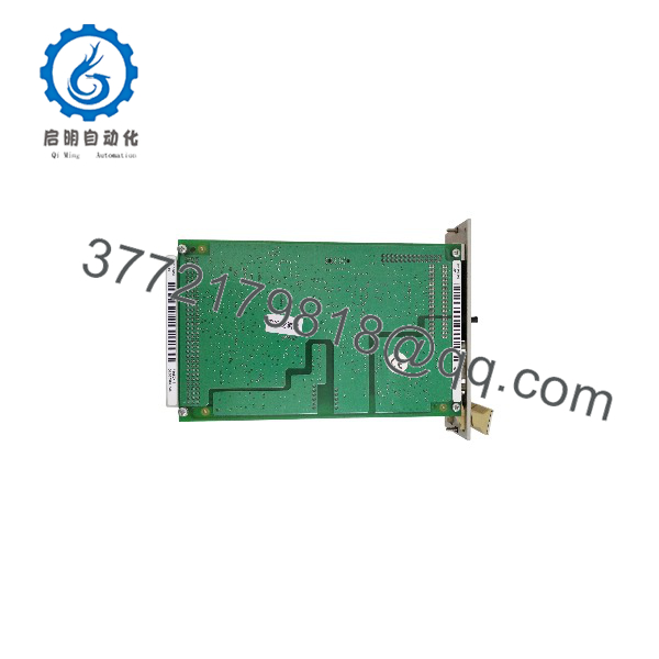
F8652X
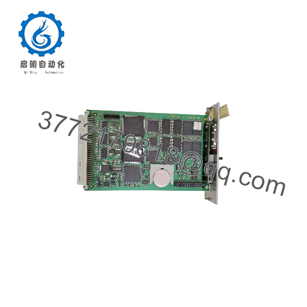
F8652X
Troubleshooting Quick Reference
| Symptom | Possible Cause | Relevance to This Part | Quick Check Method | Recommendation |
|---|---|---|---|---|
| No display or CPU LEDs after rack energization | Missing 5 V DC backplane supply, failed rack PSU, loose module seating, damaged backplane connector | ❌ Low until rack supply is verified | Measure the 5 V DC rail at the approved rack test point; check power-supply status, fuses, CPU seating, and backplane contacts | Restore stable rack power before replacing the F8652X |
| CPU display shows BATI | Buffer battery nearing end of life, battery absent, battery connection fault | ❌ Usually battery-related | Read the diagnostic display and system diagnostic buffer; inspect battery only under the approved maintenance procedure | Replace the CR2477N battery within the approved interval, back up the project, then verify retained data |
| CPU remains in STOP or safe state | Active trip input, missing permissive, invalid project, I/O fault, watchdog event, reset sequence incomplete | ❌ Usually application or field-side | Use the approved HIMA engineering environment to identify the first active trip or diagnostic; check safety input states and reset conditions | Correct the actual trip cause. Do not bypass inputs or force outputs to make the CPU run |
| CPU reports configuration fault after replacement | Wrong CPU variant, incompatible operating system, incorrect project, rack mismatch, missing configuration data | ✅ High | Compare original and replacement labels, operating-system version, project compatibility status, rack architecture, and diagnostic display | Install an exact compatible F8652X and load only the approved validated project |
| Repeated CPU resets or intermittent diagnostics | 5 V rail droop, loose rack contacts, high cabinet temperature, unstable power, internal CPU fault | ✅ Medium | Trend the 5 V DC rail during operation; inspect F7126 or equivalent rack supply, cabinet temperature, and event timestamps | Fix rack power and cooling first. Replace CPU only if the fault continues in a stable known-good rack |
| I/O fault LED is active but CPU fault LED is clear | Failed I/O module, field wiring fault, missing field supply, remote I/O problem | ❌ Usually external to CPU | Identify the specific I/O channel or module in the diagnostic buffer; inspect wiring, field device, and I/O module status | Troubleshoot the reported I/O circuit before replacing the central module |
| RS-485 device does not communicate | Station number mismatch, baud-rate mismatch, A/B pair reversed, missing termination, cable/shield fault, wrong protocol configuration | ❌ Usually configuration or wiring | Confirm S1-8 baud setting, station number, cable polarity, shield, termination, and controller diagnostics | Correct communication settings before replacing the CPU |
| Engineering PC cannot connect | Wrong software version, serial-interface settings mismatch, wrong cable, incorrect station number, PC port configuration fault | ❌ Usually host-side | Verify engineering-software version, PC interface, cable wiring, selected port, CPU station address, and baud rate | Use the documented engineering setup. Do not change live safety configuration without change control |
| Watchdog output will not energize | CPU not in valid state, output load too large, wiring open, watchdog output fault | ✅ Medium | Review CPU diagnostics; under an approved test condition, measure the 24 V DC watchdog output and confirm connected load is no more than 500 mA | Correct state and load issues first. Replace CPU only if the watchdog output fails under a known-good rated load |
| Watchdog output remains high after a fault | External relay welded, backfeed from another 24 V source, incorrect wiring, output fault | ❌ Usually external final-element circuit | Under lockout/tagout, determine whether voltage drops at the watchdog terminal; then isolate the external load | If terminal voltage drops but field equipment remains energized, repair the external relay or wiring |
| CPU cannot retain application data after outage | Battery expired, project not backed up, incorrect battery installation, memory/operating-system issue | ✅ Medium | Verify battery status and controlled power-loss retention only under approved test conditions; compare project checksum after restart | Replace battery and restore the validated project. Do not rely on assumed retention |
| New does not communicate through Ethernet | F8627/F8627X interface mismatch, incorrect network configuration, invalid station address, incompatible OS/project | ❌ Usually communication-module or configuration related | Verify Ethernet-module type, CPU station number, network settings, supported operating-system version, and diagnostics | Correct the system communication design before changing the CPU |
| CPU faults after cabinet temperature rises | Cooling fan failure, blocked airflow, wrong CPU/fan upgrade configuration, high ambient temperature | ✅ Medium | Measure cabinet temperature and inspect airflow, fan status, mounting clearance, and temperature alarms | Correct cooling before replacing the controller; keep the hardware configuration matched to HIMA guidance |
| Diagnostic error appears after maintenance | Changed switch settings, poor module seating, ESD damage, disconnected cable, altered rack configuration | ✅ Medium | Compare pre-work photos and documentation; inspect S1 settings, rack position, connector seating, and diagnostic history | Restore the original validated configuration and use ESD controls during service |
❗ Model warning: F8652, F8652A, F8652E, and are related central-module variants, but they are not automatically interchangeable. Match the complete part number, 984865265 code, operating-system version, application project, rack architecture, and software environment before a replacement.
❗ Station-address warning: Before removing the existing module, document every S1 switch setting. The CPU supports serial station numbers 1–31 and Ethernet network addresses 1–99 when used with compatible Ethernet hardware. One incorrect switch can turn a healthy replacement into an “offline CPU” problem.
❗ Battery warning: The CR2477N buffer battery has a finite retention window—up to 1,000 days at 25 °C but only about 200 days at 60 °C without supply. Replace it at least every six years or within three months of BATI. Do not wait for a prolonged outage to discover the battery is exhausted.
❗ Safety warning: This CPU is part of a safety instrumented system. Isolate the process under approved lockout/tagout, use management of change, preserve diagnostics and application backups, and perform documented post-change functional tests. A CPU display that looks normal does not prove that every ESD valve, burner trip, emergency stop, or final element works.
If you are stuck, send technical support full and 984865265 label photos, rack model, CPU display code, operating-system version, engineering-software version, 5 V rack measurement, battery status, communications configuration, controller diagnostics, and project compatibility message. Keep these checks in mind and you will save yourself most of the usual rework time.
Frequently Asked Questions
What is the HIMA ?
The HIMA is a safety-related central module for HIQuad PES H41q and H51q safety systems. It executes the approved safety application, supervises system diagnostics, communicates through two isolated RS-485 interfaces, and controls a 24 V DC safety watchdog output. Its dual Intel 386EX processors operate synchronously to detect internal processing faults and bring the system to a safe state when required.
Is the a standalone safety PLC?
Not in the modern compact-controller sense. The is the central processor within a HIQuad rack architecture. It requires a compatible H41q or H51q rack, correct 5 V DC backplane power, supporting I/O modules, field wiring, approved engineering software, and a validated safety application. It can be used in H41q-MS, H41q-HS, or H41q-HRS architectures.
What is the difference between F8652 and ?
The provides larger memory than the base F8652. The available F8652 document identifies 1 MB operating-system memory, 512 KB user program memory, and 256 KB SRAM data memory per processor for the non-X F8652. The documentation identifies 1 MB each of operating-system flash, user-program flash, and SRAM data memory per processor.
That difference matters when loading an existing project. Confirm operating-system and project requirements before treating the X module as a replacement for an older CPU.
Can I hot-swap an ?
No. Do not remove or reseat a central safety CPU under power unless an explicit HIMA-approved, site-approved procedure for the exact redundant architecture permits it. A CPU interruption can stop safety logic execution, drop watchdog output, interrupt I/O and communications, and initiate an unplanned but safe process shutdown.
Back up the application and diagnostics first, place the process in a safe state, isolate power as required, and complete all post-installation startup and functional tests.
Will I lose the safety application when replacing the CPU?
Do not assume it will transfer automatically. Retention depends on operating-system version, project-storage method, buffer-battery condition, CPU compatibility, and commissioning practice. Create a verified backup from the approved HIMA engineering environment before removal. Also record all switch settings, bus station number, communication parameters, and CPU diagnostic data.
After installation, verify the application checksum, CPU state, I/O recognition, communications, permissives, trips, resets, final-element operation, and documented proof-test steps.
What does BATI mean on the display?
BATI indicates that the buffer battery requires attention. The documented battery is a CR2477N lithium cell, HIMA part number 44 0000018. HIMA guidance recommends replacing it at least every six years or within three months of BATI indication. The battery supports retained information during loss of external supply.
Is the obsolete?
The is a legacy HIQuad CPU. Availability typically comes from New Surplus, used stock, professionally tested refurbished units, or a planned modernization path. Keep an exact-compatible spare for a critical operating unit, together with the HIMA project archive, engineering software and license, compatible PC interface, battery spares, rack drawings, CPU switch-setting record, and test procedure.
How should a New Surplus be tested before shipment?
Start with traceability and inbound inspection: verify the model, 984865265 part number, serial number, backplane contacts, RS-485 connectors, diagnostic display, ACK button, S1 switch condition, battery status, PCB condition, heat sinks, and any coating. Reject units with corrosion, damaged connectors, evidence of overheating, rework marks, cracked components, or missing hardware.
For live functional testing, install the CPU in a genuine compatible H41q/H51q test rack with a regulated 5 V DC, 2 A backplane supply, known-good I/O, and the correct engineering-software environment. Verify boot sequence, diagnostic display, CPU and I/O LED behavior, project compatibility, application loading or verification, and stable execution of a controlled safety test application.
Exercise both isolated RS-485 interfaces using known-good communication equipment. Verify station-address and baud-rate settings, then test the 24 V DC watchdog output using a monitored load of 500 mA or less. Perform controlled checks of CPU/I/O diagnostic reporting, ACK operation, battery-status indication, and retained data according to the approved test procedure.
Run the controller under representative I/O and communications load for more than 24 hours while monitoring 5 V rail stability, temperature, diagnostics, watchdog operation, communication integrity, and unexpected resets. Document the rack type, operating-system version, engineering-software version, switch settings, communication test result, watchdog result, battery result, project checksum, test duration, and QC inspector sign-off. Package in ESD-safe material with protected connectors and a foam-supported heavy-duty box. Test photos and video should be available upon request. Available HIMA documentation identifies the as a dual 25 MHz Intel 386EX safety central module with 1 MB each of OS, user-program, and data memory per processor, two isolated RS-485 interfaces, a four-digit diagnostic display, 5 V DC/2 A rack power, and a 24 V DC/500 mA safety watchdog output.



