
 WhatsApp: +86 16626708626
 Email:
  Phone: +86 16626708626
Description
3. Key Technical Specifications
| Parameter | Value |
|---|---|
| Input Voltage | 24 V DC (−15 % … +20 %), ≤ 40 mA |
| Output | Floating NO contact |
| Switching Time | Approx. 8 ms |
| Reset Time | Approx. 6 ms |
| Contact Material | AgNi, hard gold-plated |
| Switching Voltage | ≥ 5 V, ≤ 250 VAC / ≤ 220 VDC |
| Switching Current | ≥ 10 mA, ≤ 4 A |
| AC Switching Capacity | ≤ 500 VA (cos φ > 0.5); ≤ 830 VA (cos φ > 0.9) |
| Ambient Temperature | −25 °C to +60 °C |
| Degree of Protection | IP20 |
| Safety Rating | Up to SIL 3 (IEC 61508) |
| Mounting | 35 mm DIN rail / C-profile |
4. Product Introduction
The HIMA H4135A is a safety-related relay module with electronic housing designed for circuits requiring SIL 3 integrity per IEC 61508. It uses diverse relays and provides a floating normally-open contact for reliable isolation between control and field circuits.
Typical applications include emergency shutdown (ESD), fuel-supply cut-off in combustion plants, and other safety interlocks where a high-integrity switching element is required. The module is tested against multiple international standards including IEC 61508, EN 298, and NFPA requirements for combustion safety.
5. Troubleshooting Quick Reference
| Symptom | Possible Cause | Relevance to this Part | Quick Check Method | Recommendation |
|---|---|---|---|---|
| Relay does not pick up | Missing or incorrect 24 V DC supply | ✅ High | Measure voltage at input terminals | Restore correct 24 V DC supply within tolerance |
| Output contact remains open | Blown internal fuse or failed relay | ✅ High | Check fuse F1; test contact continuity when energized | Replace fuse if blown; replace module if contact fails |
| Intermittent switching | Loose terminals or vibration | ✅ Medium | Inspect and retorque terminals | Secure wiring; verify mounting is rigid |
| Contact welding or sticking | Overcurrent or inductive load without suppression | ✅ High | Verify load current ≤ 4 A and suppress inductive loads | Add freewheeling diode at inductive load; stay within ratings |
| No diagnostic indication | Fuse monitoring terminal misused | ✅ Medium | Confirm terminal 8 is used only for fuse monitoring | Do not supply voltage through the monitoring terminal |
If the fault persists after these checks, provide measured input voltage, load details, and clear photos of the wiring to technical support.
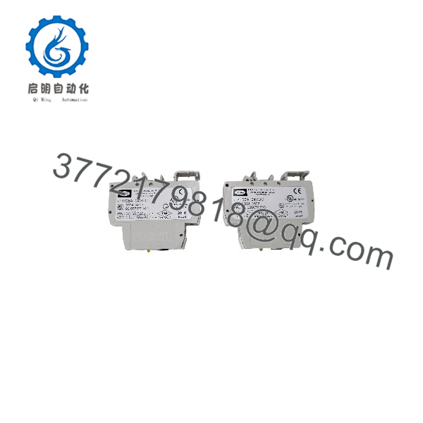
H4135A
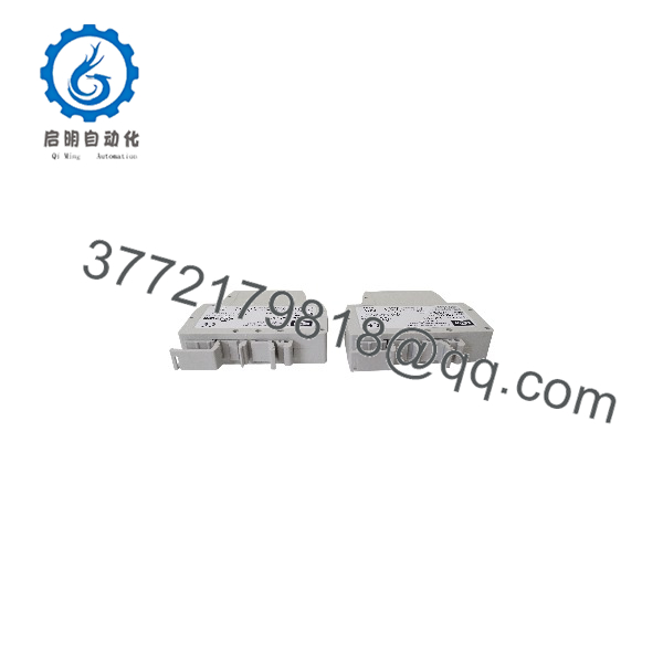
H4135A
6. Frequently Asked Questions (FAQ)
Q: What safety integrity level does the H4135A support?
A: It is certified for safety-related circuits up to SIL 3 according to IEC 61508. It is suitable for emergency shutdown and combustion safety applications when applied correctly within the safety system design.
Q: Can the H4135A be mounted in a hazardous area?
A: It can be installed in Zone 2 if placed inside a suitable IP54 (or higher) enclosure and operated only when de-energized, following the manufacturer’s special conditions of use.
Q: What is the maximum switching current?
A: 4 A continuous. Do not exceed the published AC or DC switching capacity. For inductive loads, provide external suppression at the load.
Q: Is the output contact isolated?
A: Yes. The output is a floating NO contact with safe isolation between the control input and the switched circuit.
Q: Why is secondary-market pricing often lower than list?
A: These modules appear as new surplus from completed safety-system projects or decommissioned panels. Verified units remain functional but typically carry a seller warranty rather than a current HIMA factory warranty.
Q: Does the module require special programming?
A: No. It is a hard-wired safety relay. Function is determined by the external safety logic and wiring, not by software configuration.
Q: What fuse is fitted as standard?
A: A 4 A time-lag fuse (F1) is supplied. The monitoring terminal is for fuse supervision only and must not be used as a power feed.



