
 WhatsApp: +86 16626708626
 Email:
  Phone: +86 16626708626
Description
Key Technical Specifications
| Parameter | Specification |
| Model Designation | H6200A / H 6200 A |
| Operating Voltage (U_n) | 24 VDC (18 VDC to 30 VDC operating range) |
| Functionality | Line-monitored transmitter (detects wire break and short circuit) |
| Diagnostic Indicators | Front panel LEDs: RDY (Ready / Green), F (Fault / Red) |
| Isolation | Galvanic separation between input, output, and power supply |
| Explosion Protection | ATEX Certified / Intrinsically Safe interface options (Ex) |
| Housing Construction | IP20 thermoplastic DIN rail enclosure with screw terminals |
| Mounting | Standard 35 mm DIN Rail (EN 50022) |
| Ambient Operating Temp | -25°C to +60°C |
Product Introduction & Application Context
The HIMA H6200A is a specialized safety line transmitter module engineered to extend the diagnostic coverage of HIMA safety controllers (such as HIQuad, HIMax, and Planar systems). Installed between field sensors (such as emergency stop buttons, pushbuttons, and pressure switches) and safety PLC input cards, the H6200A monitors loop impedance to distinguish between normal contact states, open-circuit wire breakage, and field cable short circuits.
In high-consequence process environments—such as burner management (BMS), turbomachinery control, and off-shore fire and gas (F&G) networks—undetected field wiring faults can cause false plant trips or lead to dangerous unresponsiveness during a safety demand. Replacing a faulty or aged H6200A unit with an exact matching module preserves the TÜV-certified SIL rating of the loop and prevents unexpected signal interrupts.
Installation & Replacement Guide
1.Circuit Isolation & Safety Verification:Disconnect line power and apply LOTO protocols.
De-energize the 24 VDC control loop feeding the H6200A module. Apply Lock-Out/Tag-Out procedures and confirm zero voltage across terminals 1 through 21 using a calibrated digital multimeter.
2.Field Wiring Disconnection:Label conductor numbers and detach screw terminals.
Label each connected wire according to the terminal numbering diagram shown on the front panel of the H6200A module. Unscrew and pull out field and power supply connections.
3.Physical Module Replacement:Release DIN rail mounting clip and swap housing.
Use a flat-blade screwdriver to pull down the lower DIN rail locking latch. Unhook the legacy module from the 35 mm rail and snap the replacement unit firmly into place.
4.Wiring & Diagnostic Verification:Reconnect conductors, reapply power, and check LEDs.
Reconnect wiring to matching screw terminals. Reapply 24 VDC system power. Verify the RDY (Ready) LED lights up solid GREEN and the F (Fault) LED remains OFF under normal loop conditions.
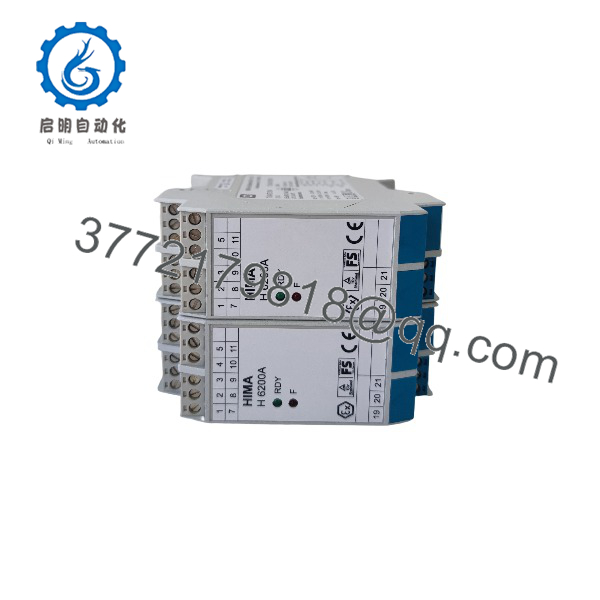
H6200A
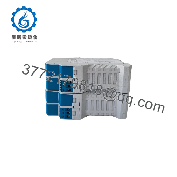
H6200A
Diagnostic LED Status Summary
- RDY (Green ON): Module power supply is healthy and internal logic is functioning normally.
- F (Red ON): Fault detected on the field line—indicates either a severed conductor (wire break) or line-to-line short circuit on the monitored field switch.
- Both LEDs OFF: Loss of 24 VDC primary power or damaged module fuse.
Frequently Asked Questions (FAQ)
Q: What is the main function of the HIMA module?
A: It provides line-monitored signal conditioning for field contacts, allowing a HIMA safety PLC to continuously verify field cable integrity and detect wire breaks or short circuits.
Q: Can the be installed in hazardous area enclosures?
A: Yes. The carries ATEX / Ex markings, allowing installation in Zone 2 hazardous areas or interfacing with intrinsically safe field circuits when installed per HIMA application guidelines.
Q: Does replacing an module require programming software adjustments?
A: No. The is a hardware-level signal conditioning transmitter module. Drop-in hardware replacement requires no software reprogramming in SILWorX or ELOP II.



