
 WhatsApp: +86 16626708626
 Email:
 Phone: +86 16626708626
Description
Core Product Summary (Brand / Model / Key Attributes)
The HIMA X-AI 32 01 (also referenced as X-AI3201) is a high-density 32-channel analog input module designed for the HIMA HIMax safety-related programmable electronic system (PES). Operating as a SIL 3 safety input unit, it evaluates up to 32 analog current signals from transmitters, sensors, and safety instrumented loops in critical process automation environments.
Capable of evaluating 0/4…20 mA analog signals, each channel is measured using two internal measuring paths to ensure safety-related diagnostic accuracy. The module features short-circuit-proof transmitter power supplies assigned to each input channel for powering 2-wire or 3-wire field transmitters up to 30 mA per point. TÜV-certified for safety-critical applications up to SIL 3 (IEC 61508 / IEC 61511), Category 4, and PL e (EN ISO 13849-1), the X-AI 32 01 interfaces with HIMax base plates via dedicated connector boards, transferring process and diagnostic data over a redundant system bus.
Key Technical Specifications
| Specification Parameter | Technical Detail |
| Product Model | X-AI 32 01 (Part / Model ID: X-AI3201 / 985210213) |
| System Architecture | HIMA HIMax Safety System |
| Number of Inputs | 32 channels |
| Signal Range | 0/4…20 mA (current input) |
| Measuring Mechanism | Dual internal measuring facilities per channel (1oo2 evaluation) |
| Safety Certification | Up to SIL 3 (IEC 61508 / IEC 61511 / IEC 62061), Cat. 4 / PL e (EN ISO 13849-1) |
| Transmitter Supply | Short-circuit-proof supply per input (up to 30 mA per channel) |
| Transmitter Compatibility | 2-wire or 3-wire analog transmitters |
| Fault State Behavior | Adopts safe state; transmits initial value (default = 0) to application logic |
| Internal Bus Interface | Redundant HIMax system bus interface |
| Isolation | Galvanically separated functional units from system bus |
| Supply Voltage | 24 VDC (SELV / PELV via system base plate) |
Detailed Product Overview
The HIMA X-AI 32 01 is an analog input slice designed for integration into HIMax safety controllers used in emergency shutdown (ESD), burner management systems (BMS), fire and gas (F&G) detection, and critical process loops. Its primary function is acquiring 0/4…20 mA field signals with safety-related measurement accuracy and transferring process data to system CPU modules over a hardware-redundant backplane.
The module incorporates 32 analog current inputs, with each input path evaluated by two internal measurement circuits. This internal architecture provides continuous hardware diagnostic cross-checks. Each channel includes an integrated, short-circuit-proof transmitter supply, allowing direct connection of 2-wire or 3-wire analog transmitters without requiring auxiliary power distribution terminals. If a hardware fault or out-of-spec condition occurs, the module forces affected input channels into a defined safe state (default process value 0) and illuminates the front-panel Error LED.
Physical mounting is achieved by inserting the X-AI 32 01 into any available input/output slot on a HIMax base plate (excluding slots reserved for system bus modules). Operating the module requires mounting onto a corresponding HIMA connector board (such as the X-CB series), which bridges field wiring via screw terminals or pre-assembled system cables connected to Field Termination Assemblies (FTAs).
Engineering Selection Highlights
- 32-Channel High Density: Accepts up to 32 analog inputs in a single HIMax slot, reducing overall rack footprint in large-scale safety instrumented systems.
- TÜV-Certified SIL 3 Compliance: Certified for use in safety loops up to SIL 3, Performance Level e (PL e), and Category 4 without requiring external voting relays.
- Dual Internal Measurement Paths: Each input circuit features two independent measuring channels for continuous hardware-level cross-monitoring.
- Integrated Short-Circuit-Proof Transmitter Power: Delivers built-in power (up to 30 mA per point) for 2-wire and 3-wire field transmitters with automated overcurrent protection.
- Fail-Safe Output State: Automatically transitions assigned variables to a defined default safe state (value 0) upon detecting channel or module hardware faults.
- Redundant Bus Integration: Communicates over the HIMax dual-redundant system backplane to ensure continuous telemetry availability.
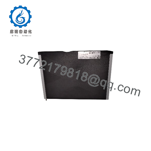
X-AI 32 01
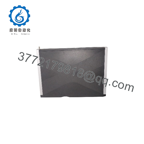
X-AI 32 01
System Compatibility & Integration Requirements
| Item / Dependency | Verified Compatibility or Requirement | Practical Note |
| System Platform | HIMA HIMax Programmable Electronic System (PES) | Installs into standard I/O slots on HIMax base plates. |
| Base Plate Slot Scope | Compatible with standard I/O slots | Cannot be inserted into dedicated system bus module slots. |
| Connector Board Fit | HIMA X-CB connector boards (e.g., X-CB 008 series) | Required for operation; provides mechanical coding and field interface. |
| Field Termination Assemblies | Optional system cable connection to HIMA FTAs | Uses HIMA X-CA system cables to connect connector boards to FTAs. |
| Engineering Tool | SILworX Programming & Configuration Software | Configured via the hardware editor in SILworX. |
| Bus Module Requirement | Dual HIMax System Bus Modules | System bus redundancy requires both system bus modules to be active in SILworX. |
Dimensions, Mounting & Connection Notes
- Mounting Style: Plug-in module design; mounts into base plate slots of the HIMax rack frame.
- Required Accessories: Must be paired with a suitable HIMA connector board (X-CB) secured via captive screws before inserting the module.
- Wiring Configurations: Supports direct field wiring via screw-terminal connector boards or prefabricated X-CA system cables linked to FTAs.
- ESD Handling Requirements: Must be handled using standard ESD protective precautions (wrist straps) during installation or replacement.
- Power Connection: Operating voltage (24 VDC) is distributed through the HIMax base plate backplane.
FAQ
What is the HIMA X-AI 32 01?
The HIMA X-AI 32 01 (also designated X-AI3201) is a 32-channel safety analog input module designed for the HIMA HIMax safety system platform.
What signal types does the X-AI 32 01 evaluate?
The module evaluates standard 0/4…20 mA analog current signals from 2-wire or 3-wire field transmitters.
What safety certification levels does the module carry?
It is TÜV-certified for safety-related applications up to SIL 3 according to IEC 61508 / IEC 61511 / IEC 62061, and PL e / Category 4 according to EN ISO 13849-1.
Does the module provide power to field transmitters?
Yes, each of the 32 channels includes an integrated, short-circuit-proof transmitter supply supplying up to 30 mA per channel.
Is the X-AI 32 01 operational as a standalone module?
No, the module requires a compatible HIMA connector board (such as the X-CB 008 series) mounted on the base plate to interface with field wiring or system cables.
How does the module react if an internal fault occurs?
Upon fault detection, the module enters a defined safe state, forces the assigned input variable to its initial configured value (default 0), and turns on the front-panel Error LED.
Which software is used to configure the X-AI 32 01?
Module parameters, filter settings, diagnostic addresses, and channel mappings are configured using HIMA SILworX software.
Verification & Troubleshooting Notes
- Front-Panel LED Inspection: Check the front-panel status LEDs (System, Error, and I/O LEDs) to distinguish normal operation from hardware fault conditions.
- Diagnostic Register Evaluation: Use SILworX diagnostic tools to monitor the module status DWORD and individual channel diagnostic bits when investigating signal anomalies.
- Transmitter Loop Checks: If a channel fails to register current, inspect field wiring for short circuits or open loops; verify that transmitter current draw remains within the 30 mA limit.
- Connector Board Seating: Ensure the X-CB connector board is fully aligned with its mechanical coding wedges and tightly secured with captive screws before inserting the X-AI 32 01 slice into the base plate.



