
 WhatsApp: +86 16626708626
 Email:
 Phone: +86 16626708626
Description
Core Product Summary
The HIMA X-CPU 01 (part no. 985210211) is the central processor module of the HIMax programmable electronic system. It executes the safety-related user programs, manages all central system functions including communication, and coordinates redundant operation with up to three additional processor modules. The module is built on a 1oo2 (one-out-of-two) processor architecture with continuous self-tests, and it is certified by TÜV for safety-related applications up to SIL 3 (IEC 61508, IEC 61511, IEC 62061), Category 4 (EN 954-1) and PL e (EN ISO 13849).
For system integration, the X-CPU 01 installs in designated slots of a HIMax base plate and requires the X-CB 001 01 connector board, which carries its four RJ-45 Ethernet interfaces for safeethernet communication and the engineering connection. The module runs on 24 VDC, is configured with the SILworX engineering tool, and may only be operated with forced cooling from an X-FAN fan rack. Its non-volatile memory holds the operating system, the user project and a 5,000-event buffer, and it processes up to 32 concurrent user programs.
Key Technical Specifications
| Parameter | Value |
|---|
| Product type | Processor module for the HIMax system |
| Part number | 985210211 |
| Safety architecture | 1oo2 — two synchronous microprocessors with testable hardware comparator and watchdog |
| Functional safety | SIL 3 (IEC 61508 / IEC 61511 / IEC 62061), Cat. 4 (EN 954-1), PL e (EN ISO 13849) |
| User programs | Up to 32 |
| Redundancy | Up to 3 additional processor modules |
| Ethernet interfaces | 4 × RJ-45, 10/100/1000 Base-T, half/full duplex, auto negotiation, auto crossover |
| Supported protocols | safeethernet, PADT (SILworX), SNTP time synchronization |
| Supply voltage | 24 VDC (monitored; < approx. 18 V rated as faulty; do not exceed 30 V) |
| Current input | 1.4 A |
| Program and data memory | 10 MB less 4 kB for CRCs |
| Retain variable memory | 32 kB |
| Date/time buffering | 5 days via gold capacitor (maintenance-free) |
| Event definitions | 20,000 |
| Non-volatile event buffer | 5,000 events |
| Diagnostic memory | 1,500 short-term / 2,500 long-term messages |
| Operating temperature | 0 °C to +60 °C (monitored by the system) |
| Storage temperature | −40 °C to +85 °C |
| Humidity | Max. 95 % relative humidity, non-condensing |
| Type of protection | IP20 |
| Protection class | III per IEC/EN 61131-2 |
| Pollution degree | II |
| Altitude | < 2,000 m |
| Dimensions (H × W × D) | 310 × 29.2 × 236 mm |
| Weight (approx.) | 1.3 kg |
| Housing material | Polyamide, fire-retardant per NFPA 72 |
Detailed Product Overview
Within a HIMax architecture, the X-CPU 01 is not an optional computing addition but the mandatory core of data processing: no HIMax system operates without at least one processor module. Its tasks span the execution of up to 32 user programs, all central functions including communication, redundancy management, safeethernet data exchange with other HIMA controllers and remote I/O, and the creation and storage of CPU events plus events forwarded from I/O modules.
The 1oo2 processor system is the basis of the module’s safety concept. Two synchronous microprocessors execute the same program in parallel, each with dedicated DDRAM, and a testable hardware comparator checks the data buses for divergence. Continuous self-tests run in the background; when the test harness detects a fault, the module enters the ERROR STOP state, restarts, and — if the fault persists across a second error stop — requires a restart from the programming and engineering tool after the cause has been eliminated. A watchdog supervises both processors, and a gold capacitor buffers date and time for five days without maintenance.
Redundancy is handled at module level. Up to three additional X-CPU 01 modules can be operated together, and the group automatically determines startup order and operating state. This has a direct maintenance consequence: in a properly configured redundant system, an individual processor module can be replaced without interrupting operation, because the external wiring terminates on the connector board, which stays in the base plate when the module is withdrawn. The module’s slot resource identifier (SRS) is stored on the connector board and is re-adopted when a module is plugged back in.
Communication runs through a four-port Ethernet switch located on the module, with the physical RJ-45 connectors on the X-CB 001 01 connector board. safeethernet is the safety-related protocol used between HIMax systems, HIMatrix controllers and remote I/O; UDP port 6010 serves safeethernet, port 8000 the SILworX engineering connection, port 8001 remote I/O configuration, and port 123 time synchronization. The integrated switch supports per-port speed, duplex and broadcast/multicast limiting settings, configurable in SILworX.
Event handling deserves attention during sizing. The module distinguishes Boolean and scalar events with up to two upper and two lower limits and configurable hysteresis, supports up to 20,000 event definitions, and stores 5,000 events in a non-volatile buffer that survives power loss. Sequence-of-events (SOE) capable I/O modules timestamp at source; otherwise the CPU timestamps. A separate diagnostic memory holds 1,500 short-term and 2,500 long-term diagnostic messages readable from the engineering station.
Maintenance is defined rather than optional: the operating system should be updated during scheduled downtimes, and HIMax modules must pass a proof test at intervals of 10 years in accordance with the system safety requirements. Defective modules are replaced with a faultless module of the same type or an approved replacement model; repair is reserved for the manufacturer.
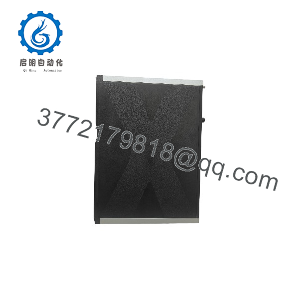
X-CPU 01
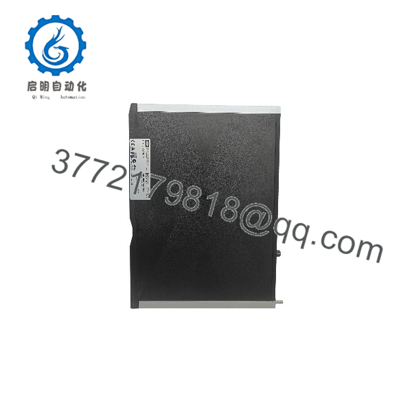
X-CPU 01
System Compatibility & Integration Requirements
| Item / Dependency | Verified Compatibility or Requirement | Practical Note |
|---|
| System family | HIMax programmable electronic system | The processor module is mandatory for HIMax operation |
| Base plate slots | Rack 0, slots 3–6; redundant modules may be distributed across racks 0 and 1 (slots 3 and 4) | For mono operation: slot 3 plus at least one system bus module in slot 1; redundant configurations require system buses A + B |
| Recommended slot variant | Two processor modules in slots 3 and 4 of rack 0 | Recommended so a processor module can be replaced without interrupting operation |
| Connector board | X-CB 001 01 (mandatory, not included in the module’s scope of delivery) | Carries the four RJ-45 ports (Eth1–Eth4); module and connector board form one functional unit |
| Forced cooling | X-FAN fan rack (or approved replacement type) | Operation without forced cooling is not permitted; temperature is monitored (thresholds at 40 °C and 60 °C) |
| Supply | 24 VDC via base plate (L1+/L1−, L2+/L2−) | Supply below approx. 18 V is rated faulty; never connect more than 30 V |
| Engineering software | SILworX (PADT) | Used for configuration, event setup, diagnosis and OS loading |
| Communication partners | HIMax, HIMatrix and remote I/O modules via safeethernet | An Ethernet cable is needed for the PADT connection (not included with the module) |
| Replacement | Faultless module of the same type or approved replacement model | Only the manufacturer is authorized to repair the module |
Dimensions, Mounting & Connection Notes
- Dimensions (H × W × D): 310 × 29.2 × 236 mm; weight approx. 1.3 kg; degree of protection IP20.
- The module mounts in a HIMax base plate: hook the top of the module into the hook-in rail, swivel the lower edge toward the base plate until it snaps in, then tighten the fixing screws. Required tools: slotted screwdrivers 0.8 × 4.0 mm and 1.2 × 8.0 mm.
- Mounting and removal are possible while the HIMax system is operating. When doing so, the fan rack cover plate may remain open only for a few minutes (under 10 minutes), since forced cooling is affected. When the module is removed, the connector board remains in the base plate, so the external interfaces stay untouched.
- The X-CB 001 01 connector board installs on the guiding rail (groove facing upward), seats on the cable shield rail, and is secured with two captive screws — lower screw first, then the upper.
- All external connections are made through the connector board: four RJ-45 sockets (Eth1/X3 through Eth4/X6) with standard-compliant pin assignment, supporting 10/100/1000 Base-T with auto negotiation and auto crossover.
- Observe ESD precautions: work at a static-free workstation with an ESD wrist strap; keep unused modules in their protective packaging.
- Environmental limits: 0 °C to +60 °C operating (system-monitored), −40 °C to +85 °C storage, max. 95 % relative humidity non-condensing, installation altitude below 2,000 m, pollution degree II.
FAQ
What is the HIMA X-CPU 01? It is the central processor module of the HIMax safety-related programmable electronic system. It executes up to 32 user programs, performs all central functions including communication, manages redundancy with up to three additional processor modules, and handles safeethernet communication and event storage.
Which safety integrity level does the X-CPU 01 support? The module is TÜV-certified for safety-related applications up to SIL 3 per IEC 61508, IEC 61511 and IEC 62061, Category 4 per EN 954-1, and PL e per EN ISO 13849.
How does the 1oo2 architecture work? Two synchronous microprocessors execute the program in parallel, each with dedicated memory. A testable hardware comparator continuously compares the data buses, a watchdog supervises both processors, and self-tests run continuously. On detection of a fault, the module enters ERROR STOP and restarts.
Which slots can the X-CPU 01 be installed in? Processor modules operate in slots 3 to 6 of rack 0, with system buses A and B required. For mono operation, one module in slot 3 plus at least one system bus module in slot 1 is required. Redundant configurations may distribute modules across racks 0 and 1; a redundant pair in rack 0 slots 3 and 4 is the recommended arrangement.
Is a connector board required? Yes. The module can only operate when installed on the X-CB 001 01 connector board, which carries the four Ethernet ports. The connector board is not included in the module’s delivery scope, and it remains in the base plate when the module is exchanged.
Which software is used to configure the module? The SILworX engineering tool (PADT) is used for hardware configuration, IP and switch settings, event configuration, diagnosis and operating-system loading. Communication uses UDP ports 8000 (SILworX), 8001 (remote I/O configuration), 6010 (safeethernet) and 123 (SNTP).
Can the module be replaced during operation? In a redundant configuration, yes: the module is withdrawn and inserted while the system runs, and it adopts the stored configuration. The fan rack cover may only be open for a few minutes. Note that in mono operation the module is absolutely required for system operation.
What are the power and environmental requirements? The module is supplied with 24 VDC from the base plate and draws 1.4 A. Operation requires forced cooling via the X-FAN fan rack, an ambient temperature of 0 °C to +60 °C, and installation at altitudes below 2,000 m.
What maintenance does the module require? Operating-system updates are loaded during system downtimes, and a proof test must be carried out at intervals of 10 years. Defective modules are replaced with a faultless module of the same type or an approved replacement model; repair is performed only by the manufacturer.



