
 WhatsApp: +86 16626708626
 Email:
  Phone: +86 16626708626
Description
Key Technical Specifications
| Parameter | Value |
|---|---|
| Model | AB7312-B |
| Manufacturer | HMS Networks |
| Brand | Anybus |
| Product Type | Industrial protocol converter |
| CAN Mode | Generic CAN |
| CAN Standard | CAN 2.0A / 2.0B |
| CAN Identifier | 11-bit and 29-bit |
| CAN Baud Rate | 20 kbit/s to 1 Mbit/s |
| CAN Transactions | 128 transactions / up to 256 CAN frames |
| PROFIBUS Mode | DP Device / PROFIBUS DP-V1 Slave |
| PROFIBUS Baud Rate | 9.6 kbit/s to 12 Mbit/s |
| PROFIBUS Address | 0-125 |
| PROFIBUS Input Data | 244 bytes; 344 bytes maximum total input + output |
| PROFIBUS Output Data | 244 bytes; 344 bytes maximum total input + output |
| PROFIBUS Functions | DP-V1 Class 1 & 2, Sync, Freeze, Watchdog |
| CAN Functions | Produce, Consume, Query/Response, Cyclic, On Data Change, Single Shot, Trigger Byte |
| Supply Voltage | 24 V DC ±10% |
| Current Consumption | 100 mA typical; 250 mA maximum at 24 V DC |
| Mounting | DIN rail, EN 50022 |
| Protection | IP20 |
| Operating Temperature | -25 to +55 °C |
| Storage Temperature | -40 to +85 °C |
| Dimensions | 120 × 75 × 27 mm |
| Weight | 150 g |
| PROFIBUS Connector | 9-pin D-sub |
| Power Connector | 2-pin, 5.08 mm Phoenix plug |
| Protection Features | Reverse-polarity and short-circuit protection |
| Configuration | GSD file available |
These values come directly from HMS’s current product specification and datasheet.
Product Introduction
The HMS Networks AB7312-B Anybus Communicator is an industrial protocol gateway that connects CAN-based field equipment to a PROFIBUS DP control system. It supports generic CAN as well as CAN 2.0A and 2.0B, including 11-bit and 29-bit identifiers.
On the PROFIBUS side, the AB7312-B operates as a DP/DP-V1 slave with device addresses from 0 to 125 and communication speeds up to 12 Mbit/s. Typical applications include CAN-based drives, sensors, actuators, HMIs, barcode readers, RFID equipment, and industrial scales.
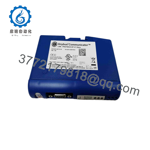
AB7312-B
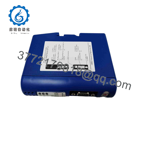
AB7312-B
Installation & Configuration Guide
Stage 1: Pre-Installation Preparation — About 10 Minutes
⚠️ Safety First: Put the affected equipment into its approved safe state before changing the gateway. Follow the plant’s lockout/tagout procedure and isolate the 24 V DC supply before disconnecting wiring.
Tools Required:
- ESD wrist strap
- Digital multimeter
- Small screwdriver
- Wire labels
- Smartphone or camera
- PROFIBUS diagnostic software or PLC engineering software
Data Backup:
- Record the complete AB7312-B part number.
- Photograph the CAN and PROFIBUS connections.
- Record the PROFIBUS station address.
- Record the CAN baud rate.
- Document the CAN identifier format: 11-bit or 29-bit.
- Back up the existing Anybus configuration if the original gateway is still accessible.
- Save the PROFIBUS master configuration and GSD file used by the project.
Stage 2: Removing the Old Module — About 5 Minutes
- Confirm that the connected equipment is in a safe state.
- Isolate the 24 V DC supply.
- Photograph all connections before removal.
- Label the CAN wiring and PROFIBUS connector.
- Disconnect the CAN interface.
- Disconnect the PROFIBUS connector.
- Disconnect the 24 V DC supply.
- Release the DIN-rail mounting mechanism.
- Remove the gateway without placing mechanical stress on the cables.
⚠️ Do not assume the CAN network will work simply because the gateway powers up. CAN baud rate, identifier format, frame mapping, and transaction configuration must agree with the connected equipment.
Stage 3: Installing the New Module — About 5 Minutes
- Establish ESD protection.
- Verify the replacement is AB7312-B.
- Inspect the housing and connectors for damage.
- Mount the gateway on the EN 50022 DIN rail.
- Connect the 24 V DC supply with correct polarity.
- Connect the CAN interface.
- Connect the PROFIBUS cable.
- Set the PROFIBUS address to match the original installation.
- Verify the PROFIBUS segment termination.
- Load or reproduce the documented CAN transaction configuration.
Self-Checklist:
- AB7312-B part number verified
- 24 V DC polarity checked
- CAN wiring verified
- CAN baud rate verified
- 11-bit/29-bit identifier format checked
- PROFIBUS address verified
- GSD configuration confirmed
- PROFIBUS termination checked
Stage 4: Power-On & Testing — About 10-15 Minutes
- Perform a final wiring inspection.
- Check the 24 V DC supply with a multimeter.
- Power the .
- Check the gateway status indications.
- Verify the PROFIBUS master detects the configured slave.
- Confirm the PROFIBUS address.
- Verify the CAN network is receiving the expected frames.
- Confirm CAN-to-PROFIBUS data mapping.
- Test the required cyclic or event-driven transactions.
- Check diagnostic information before returning the equipment to normal operation.
⚠️ Pay particular attention to data direction. The supports multiple CAN transaction modes, including Produce, Consume, Query/Response, Cyclic, On Data Change, Single Shot, and Trigger Byte operation. Incorrect transaction configuration can produce a healthy-looking PROFIBUS connection with incorrect process data.
Troubleshooting Note: If PROFIBUS does not establish communication, check the station address, GSD configuration, connector, cable, and termination. If PROFIBUS is healthy but CAN data is missing, check CAN baud rate, identifier type, frame mapping, and the configured CAN transaction mode.
Frequently Asked Questions (FAQ)
What is the HMS used for?
The connects CAN-based devices to PROFIBUS control systems. It is specifically the Anybus Communicator CAN-to-PROFIBUS DP-V1 model.
Does support CANopen?
Yes. HMS states that the Communicator can convert CANopen as well as custom CAN 1.0, CAN 2.0A, and CAN 2.0B protocols. The generic CAN interface supports 11-bit and 29-bit identifiers.
What CAN baud rates are supported?
The documented CAN baud-rate range is 20 kbit/s to 1 Mbit/s. Before replacement, record the existing CAN network speed rather than assuming the default configuration.
What PROFIBUS baud rates are supported?
The supports PROFIBUS baud rates from 9.6 kbit/s to 12 Mbit/s. It operates as a PROFIBUS DP/DP-V1 slave and supports addresses from 0 to 125.
What is the maximum PROFIBUS data size?
HMS specifies 244 bytes of input data and 244 bytes of output data, with a maximum combined input/output figure of 344 bytes for the configured PROFIBUS data. The actual usable data size depends on the configuration.
Does require a special PLC?
No. The gateway is designed to operate with PROFIBUS control systems and is not restricted to one PLC manufacturer. The PROFIBUS side uses a GSD configuration file, while the CAN side is configured for the connected device or protocol.
Is still an active product?
HMS’s current product page still provides technical specifications and ordering information for , so it should not be classified as obsolete solely because it is an older Anybus generation. For a new project, however, verify current lifecycle status and available support before committing to long-term inventory.



