
 WhatsApp: +86 16626708626
 Email:
  Phone: +86 16626708626
Description
Key Technical Specifications
| Parameter | Value |
| Primary Interface | PROFIBUS DP-V0 / DP-V1 Slave |
| Fieldbus Baud Rate | 9.6 kbps to 12 Mbps (Auto-detection) |
| Secondary Interface | RS232 / RS485 (Software/DIP selectable) |
| Serial Protocol | Modbus RTU / Modbus ASCII (Master/Slave mode) |
| Serial Baud Rate | 1,200 bps to 115,200 bps |
| Input Power Voltage | 24 V DC (\pm 15\%) |
| Power Consumption | < 3.5 W |
| Isolation Rating | 1,500 V AC (Fieldbus to Power / Serial) |
| Status Indicators | RUN, COM, RXD, TXD, ERR LEDs |
| Mounting Style | 35 mm DIN Rail Mount |
| Operating Temperature | −10 to +60 °C (+14 to +140 °F) |
| Housing Enclosure | IP20 Rated Heavy-Duty ABS Plastic |
Product Introduction & Supply Chain Strategy
The Hollysys FM020 is a specialized industrial communication gateway module designed to bridge PROFIBUS DP fieldbus networks with Modbus serial sub-networks. Used extensively in DCS implementations across power generation, petrochemical processing, and water treatment facilities, the FM020 translates data packets between central controllers and field devices such as smart meters, variable frequency drives, and third-party PLCs.
Securing the FM020 as New Surplus provides a reliable strategy to maintain legacy DCS infrastructure without executing costly system-wide control upgrades. Sourcing factory-original New Surplus units eliminates the severe downtime risks inherent to refurbished modules, which frequently feature degraded serial optocouplers, dried-out power capacitors, and unstable communication transceivers. Maintaining 1–2 units as on-site safety buffer stock guarantees immediate restoration of critical data links during hardware failures.
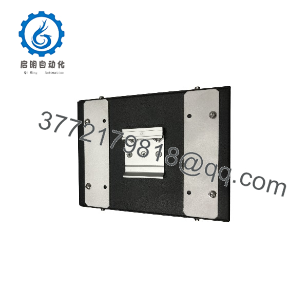
FM020
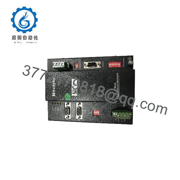
FM020
Installation & Configuration Guide
Stage 1: Pre-Installation (Prep & Safety)
- Perform Lock-Out/Tag-Out (LOTO) procedures on cabinet 24 V DC power supplies before servicing.
- Put on an ESD-grounded wrist strap to protect internal optocouplers and microcontrollers from electrostatic discharge.
- Record the physical DIP switch settings (PROFIBUS node address, line termination resistor states) on the existing module.
- Verify field wiring termination labels for RS485 (A/+, B/-) and RS232 (Tx, Rx, GND).
Stage 2: Removal
- Unplug the 9-pin Sub-D PROFIBUS connectors and removable screw terminal blocks for power and serial wiring.
- Release the DIN-rail locking latch on the base of the housing using a flat-head screwdriver.
- Carefully lift the FM020 off the 35 mm mounting rail, taking care not to pull on surrounding fieldbus cables.
Stage 3: Installation (Clone & Seat)
- Set the DIP switches on the new FM020 module to replicate the exact node address and termination resistance of the original unit.
- Snap the replacement module firmly onto the 35 mm DIN rail until the spring latch clicks into place.
- Reattach the power and serial screw terminal blocks, verifying correct wire polarity (24 V DC and ground).
- Connect the 9-pin PROFIBUS Sub-D cables, ensuring connector jack-screws are hand-tightened.
Stage 4: Power-On & Testing
- Apply 24 V DC auxiliary power and observe the power-on self-test LED sequence.
- Verify that the RUN LED illuminates solid green and the COM LED flashes to indicate active fieldbus polling.
- Monitor Tx/Rx LEDs on the serial port side to confirm bidirectional Modbus data transfer.
- Check the central DCS or PLC diagnostic buffer for zero PROFIBUS slave communication faults (Code 0x00).
Firmware/Software Versions & Upgrade Notes
- GSD File Requirement: Ensure the central PROFIBUS Master controller uses the correct
.GSDfile matching the FM020 hardware revision. Using a generic or mismatched GSD file will result in I/O configuration errors and bus fault alarms. - Serial Buffer Allocation: The internal data mapping table must match the memory configuration defined in the Modbus Master/Slave setup. Firmware revisions dictate maximum byte length per request cycle; verify data mapping profiles prior to commissioning.
- Firmware Maintenance: Avoid updating module firmware during routine maintenance or hardware swaps unless explicitly recommended by technical support to resolve documented bus timing anomalies.
Frequently Asked Questions (FAQ)
Q: How can I be sure this module is genuine New Surplus and not refurbished?
A: This product is a Brand New Surplus unit. It is not used, not pulled from a decommissioned plant, and not refurbished. All modules undergo rigorous quality verification to ensure OEM-level reliability. Each unit features factory-original terminal blocks, pristine connector pins, unmarred mounting latches, and complete QC test documentation.
Q: Why is New Surplus priced higher than refurbished modules available online?
A: Our pricing reflects the cost of securing genuine New Surplus inventory globally. It may be 20-30% higher than a refurbished gamble, but it is substantially less than OEM list prices, and it buys you 100% peace of mind. Refurbished gateway modules often contain aged voltage regulators and worn RS485 communication chips, leading to intermittent packet drops and unexpected plant outages.
Q: Does changing the DIP switch address require a power cycle on the ?
A: Yes. The reads its hardware DIP switch configurations (such as PROFIBUS node address and serial baud rate) only during initial power-up initialization. Any DIP switch adjustment made while the unit is powered will not take effect until power is cycled.
Q: Can the operate as both a Modbus Master and a Modbus Slave?
A: Yes. The module configuration utility allows you to define the serial side as either a Modbus RTU/ASCII Master (polling field instruments) or a Modbus Slave (responding to requests from a host system) while maintaining its primary function as a PROFIBUS DP Slave.
Q: What warranty is provided with this New Surplus module?
A: All New Surplus units are covered by a comprehensive 1-Year functional warranty. This guarantees that the operates according to factory specifications and provides reliable, long-term service in your control system.



