
 WhatsApp: +86 16626708626
 Email:
  Phone: +86 16626708626
Description
Key Technical Specifications
| Parameter | Value |
| Processor Type | 32-bit High-Performance Industrial Microprocessor |
| System Memory | High-Speed Static RAM with Battery Backup |
| Redundancy Support | Dual-Hot Standby Redundancy (Bumpables Transfer) |
| System Bus Interface | Dual-Redundant CNET / SNET Control Network Ports |
| Auxiliary Ports | RS232 / RS485 Engineering Console Interface |
| Input Power Voltage | 24 V DC (\pm 10\%) via Rack Backplane |
| Power Consumption | < 8.5 W |
| Diagnostic LEDs | RUN, STANDBY, CNET, ERROR, SNET1, SNET2, RNET, POWER |
| Battery Backup | On-board Lithium Battery for Data Retention |
| Form Factor | Metal Enclosure Eurocard Rack-Slot Module |
| Operating Temperature | 0 to +55 °C (+32 to +131 °F) |
| Relative Humidity | 10% to 95% (Non-condensing) |
Product Introduction & Supply Chain Strategy
The Hollysys FM801 is the central Main Control Unit (MCU) for Hollysys distributed control systems (DCS). It executes complex IEC 61131-3 algorithms, processes analog and digital I/O data streams across system backplanes, and manages real-time, deterministic communications across redundant plant networks. Designed for continuous industrial process applications, it supports dual-hot standby deployment to ensure uninterrupted loop control during hardware maintenance.
Procuring this module as New Surplus provides a strategic alternative to expensive full-system control migrations when factory-direct inventory is obsolete or subject to extended lead times. Utilizing original New Surplus units protects operations from the high risk of refurbished controller cards, which frequently harbor thermal-stress degradation, unstable RAM chips, or failing onboard lithium battery circuits. Keeping 1–2 verified FM801 units as safety buffer stock guarantees rapid restoration of critical DCS nodes, minimizing total cost of ownership (TCO) and avoiding severe production outages.
Installation & Configuration Guide
Stage 1: Pre-Installation (Prep & Safety)
- Execute full Lock-Out/Tag-Out (LOTO) protocols on the DCS rack power supplies before inserting or extracting processor hardware.
- Wear an ESD-grounded wrist strap to prevent static discharges from damaging sensitive memory and processing circuitry.
- Verify that the memory backup battery on the FM801 is fresh and the front-panel BATTERY switch is set to the ON position.
- Record and archive all current project files, IP configurations, node numbers, and control station parameters from the host engineering software.
Stage 2: Removal
- Unplug the engineering console communications cable and network patch cords connected to the front panel or rack interfaces.
- Loosen the top and bottom captive thumbscrews securing the FM801 faceplate to the card cage chassis.
- Slide the module straight out of the backplane guide rails using the insertion/extraction handle to prevent bending edge-connector pins.
Stage 3: Installation (Clone & Seat)
- Verify that hardware DIP switches or jumper arrays on the replacement FM801 match the node address configuration of the removed unit.
- Align the replacement module with the rack guide rails and push it firmly into the slot until the backplane connectors seat completely.
- Tighten top and bottom panel thumbscrews to secure the unit against vibration and ensure reliable chassis grounding.
- Reconnect network cables, ensuring redundant channels (SNET1 / SNET2) are connected to their designated switches.
Stage 4: Power-On & Testing
- Re-energize the 24 V DC system rack power supply and observe the front-panel LED power-up sequence.
- Verify that the POWER LED lights up solid and the RUN or STANDBY LED illuminates based on the redundancy state.
- Connect the engineering workstation and download the verified control project to the FM801 processor.
- Perform a functional handshake check to ensure smooth bump-free transfer between Primary and Standby controllers.
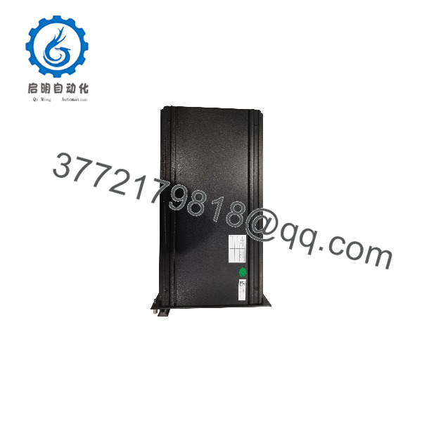
FM801
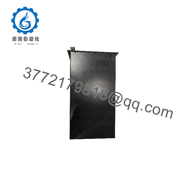
FM801
Firmware/Software Versions & Upgrade Notes
- System Software Compatibility: The requires specific HOLLiAS DCS engineering software versions (e.g., MacACS or HOLLiAS MACS toolsets). Ensure the module firmware version matches the current software release deployed across the plant network.
- Firmware Synchronization: In a dual-redundant configuration, both the Primary and Standby modules must run identical firmware build numbers. Firmware mismatches will prevent synchronization, forcing the backup unit into an ERROR or non-redundant state.
- Logic Download Safety: Never attempt a cold firmware upgrade on a live processing node. Download project files and perform system updates only during planned turnaround windows or while the secondary unit is safely isolated in Standby mode.
Frequently Asked Questions (FAQ)
Q: How can I confirm this module is genuine New Surplus and not refurbished?
A: This product is a Brand New Surplus unit. It is not used, not pulled from a decommissioned plant, and not refurbished. All modules undergo rigorous quality verification to ensure OEM-level reliability. Every unit features spotless gold-plated backplane contacts, pristine front-panel anodizing, original unmarred mounting screws, and complete QC inspection reports.
Q: Why does New Surplus carry a higher price than refurbished modules sold elsewhere?
A: Our pricing reflects the cost of securing genuine New Surplus inventory globally. It may be 20-30% higher than a refurbished gamble, but it is substantially less than OEM list prices, and it buys you 100% peace of mind. Refurbished processor cards often suffer from invisible silicon aging, degraded capacitor banks, and unreliable memory retention, which can cause unannounced controller crashes and multi-million-dollar plant shutdowns.
Q: What is the purpose of the BATTERY switch on the front panel?
A: The front-panel BATTERY switch controls the onboard lithium battery circuit that maintains the static RAM contents (retentive variables, system logs, and project configuration) when external 24 V DC backplane power is disconnected. It should be switched ON during installation and switched OFF during long-term shelf storage to prevent battery drain.
Q: Can the be replaced online without shutting down the process?
A: Yes, provided the system is running in a verified dual-redundant MCU configuration. When replacing a failed secondary module, the new unit can be inserted into the rack, where it will automatically perform self-diagnostics, synchronize memory with the active primary unit, and enter STANDBY mode without interrupting live loop control.
Q: What warranty coverage comes with this New Surplus controller?
A: All New Surplus units are covered by a solid 1-Year functional warranty. This guarantees that the meets original Hollysys factory performance standards for processing speed, network throughput, and hardware stability.



