
 WhatsApp: +86 16626708626
 Email:
  Phone: +86 16626708626
Description
Key Technical Specifications
- Model: SM711
- System: HollySys MACS-SM DCS
- I/O Type: Digital output
- Number of Channels: 16
- Output Signal: Darlington optocoupler output
- Output Current: 50 mA/channel
- Module Supply: 5.1 VDC ±3% / 24.5 VDC ±5%
- Maximum Current Consumption: 350 mA at 5.1 V; 350 mA at 24.5 V
- System Interface: 64-pin European connector
- Isolation: ≥500 VAC for 1 minute between field and system sides
- Channel-to-Channel Isolation: 250 Vrms
- Operating Temperature: 0°C to 50°C
- Operating Humidity: 5% to 95% RH, non-condensing
- Installation: Chassis/rack-mounted plug-in module
- Terminal Modules: SM3710, SM3711, SM3712, SM3713, SM3714 depending on field output requirements
The SM711 documentation identifies the module as a 16-channel digital output unit for the MACS-SM DCS family. Published technical data specifies 50 mA per channel and dual 5.1 VDC/24.5 VDC supply requirements.
The module can also participate in redundant output arrangements. For example, the published MACS-SM documentation lists SM3720 as the associated redundant output terminal module and specifies a configuration using two SM711 modules.
Product Introduction
The HollySys SM711 is a 16-channel digital output module for the MACS-SM DCS platform. It provides Darlington optocoupler outputs for driving field-side discrete devices and connects to the system chassis through a 64-pin European connector. Published specifications rate each output at 50 mA.
The module uses 5.1 VDC and 24.5 VDC system supplies and provides field-to-system isolation. SM711 is also used in redundant digital-output configurations with the appropriate terminal hardware. Verify the exact terminal module and system revision before replacing an installed unit.
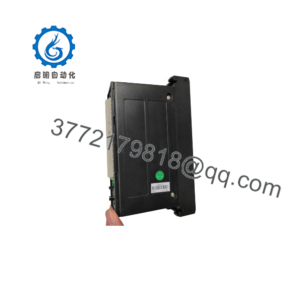
SM711
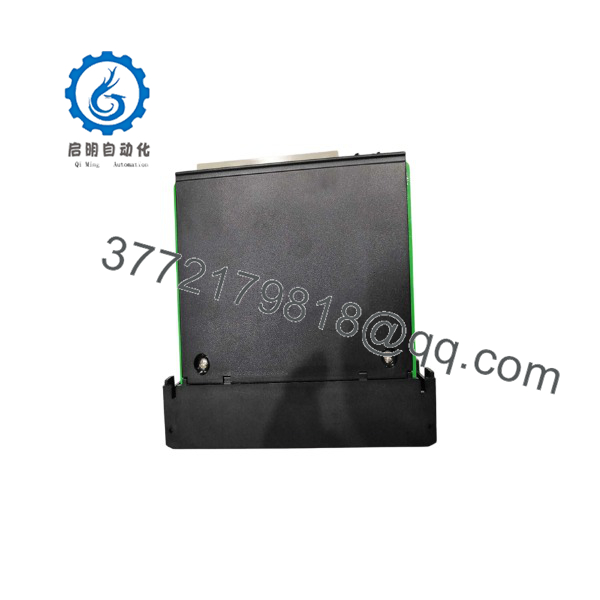
SM711
Installation & Configuration Guide
Stage 1: Pre-Installation Preparation — Approximately 5 Minutes
⚠️ Safety First: Notify operations before removing the module. Put the controlled process into its approved safe state and follow the site’s LOTO procedure. Do not assume the module can be removed under power simply because other MACS-SM hardware may support online maintenance.
Tools Required:
- ESD wrist strap
- PH1 screwdriver
- Digital multimeter
- Wire labels
- Smartphone or camera
- Appropriate terminal screwdriver
Data Backup:
- Record the installed module’s exact model and revision.
- Photograph the front panel, terminal wiring, slot position, and connector arrangement.
- Record the associated terminal module model.
- Save the current DCS configuration before disturbing the hardware.
- Record controller/I/O diagnostics if the existing SM711 is already reporting faults.
⚠️ Important: The is not simply a generic 16-point transistor output card. The terminal module, chassis slot, DCS configuration, and redundancy arrangement all matter.
Stage 2: Removing the Old Module — Approximately 5 Minutes
- Place the system in the approved maintenance state.
- Remove the front cover or bezel if fitted.
- Label every field connection before disconnecting it.
- Disconnect the associated wiring without pulling on individual conductors.
- Release the module’s mechanical locking mechanism.
- Pull the straight out of the chassis.
- Inspect the backplane connector for contamination, damaged contacts, or bent pins.
⚠️ Do not discard the old module yet. Keep it beside the replacement until commissioning is complete. Its switch, label, revision, and wiring arrangement are valuable references if something does not match.
Stage 3: Installing the New Module — Approximately 5 Minutes
- Put on the grounded ESD wrist strap.
- Verify the replacement is marked and matches the required hardware revision.
- Compare the replacement with the old unit before insertion.
- Check the chassis slot and connector alignment.
- Insert the module straight into the rack.
- Engage the locking mechanism fully.
- Reconnect the field wiring according to the documented wiring arrangement.
- Tighten terminals using the applicable terminal-block torque specification.
Configuration Clone — Critical:
The installation depends heavily on the surrounding MACS-SM hardware. Confirm:
- Correct chassis slot
- Correct terminal module
- Correct output-channel assignment
- Correct redundancy arrangement, if applicable
- Correct DCS I/O configuration
Self-Checklist:
- Correct model
- Correct chassis slot
- Correct terminal module
- Wiring labels verified
- Connector fully seated
- Locking mechanism engaged
- No loose conductors
Stage 4: Power-On & Testing — Approximately 10 Minutes
Pre-Power Check:
- Inspect the 5.1 VDC and 24.5 VDC supply rails.
- Check for accidental shorts before energizing the rack.
- Verify field wiring against the approved drawings.
Power-On:
- Energize the rack according to the plant startup procedure.
- Observe module status indicators.
- Check the DCS hardware diagnostic screen.
- Confirm that the appears in the expected I/O slot.
- Check every configured digital output point.
- Perform a controlled dry-run with the field equipment isolated where practical.
- Restore field devices only after output states have been verified.
⚠️ Troubleshooting Note: If the module is not recognized, do not immediately assume the is defective. First check the chassis slot, backplane connection, DCS configuration, terminal module, supply rails, and system hardware revision.
The published MACS-SM material identifies Profibus-DP as the communication path used by the SM-series I/O architecture, so communication faults should also be investigated at the controller/bus level rather than treating the as an independent Ethernet device.
Technical Pitfalls Worth Checking
❗ Firmware / Hardware Revision: Older DCS installations can contain revision-specific hardware. Record the existing module revision before replacement and verify compatibility with the installed MACS-SM configuration.
❗ Terminal Module Mismatch: can be paired with different output terminal modules for different field-side requirements. For example, published documentation lists SM3710 for AC relay outputs, SM3711 for DC relay outputs, and SM3712 for AC/DC solid-state relay applications.
❗ Output Current: The ‘s published output rating is 50 mA/channel. Do not connect a field load simply because its voltage appears compatible. Check the actual load current and the electrical characteristics of the associated terminal hardware.
❗ Redundant Configuration: If the original system uses redundant modules, replacing only one card without checking the redundancy configuration can create a diagnostic or switchover problem. The published SM-series documentation describes a two- arrangement with an SM3720 redundant output terminal module.
Frequently Asked Questions (FAQ)
Can the HollySys be hot-swapped?
Do not assume hot swapping is permitted for the solely because some MACS-SM modules support online replacement. The published SM-series documentation describes hot-plug capability for certain modules, but the -specific replacement procedure should be checked against the installed chassis and system revision. For a production shutdown replacement, de-energized removal is the conservative procedure.
Is the a digital input or digital output module?
It is a 16-channel digital output module. The published documentation identifies it as a 16-channel switching output module using Darlington optocoupler outputs, with a rated output current of 50 mA per channel.
What terminal module should I use with ?
That depends on the field-side load. Published MACS-SM documentation lists SM3710, SM3711, SM3712, SM3713, and SM3714 terminal modules for different output arrangements. Do not substitute one based only on physical fit; verify the field voltage, load current, and required isolation/output technology.
Can two modules be used for redundancy?
Yes, the MACS-SM documentation describes redundant digital-output configurations. It specifically identifies SM3720 as the redundant output terminal module and describes a configuration using two modules. The exact configuration must match the DCS engineering database and hardware arrangement.
Will replacing the erase my DCS programming?
Replacing the physical I/O module does not normally mean that the DCS control strategy is erased from the controller. The real risk is configuration mismatch: wrong slot assignment, incorrect I/O channel mapping, incompatible hardware revision, or an incorrect terminal-module arrangement. Back up the DCS configuration before starting the replacement.
Is an obsolete model?
The belongs to the older HollySys MACS-SM hardware family. Current replacement availability should be treated as inventory-dependent rather than assuming OEM production status. For a legacy plant, verify the installed controller, chassis, terminal module, and system revision before committing to a replacement.
Why can surplus units cost less than OEM list pricing?
Legacy automation hardware frequently enters the secondary market through plant decommissioning, project overstock, and unused maintenance inventory. The important distinction is condition, not simply price. A New Original/New Surplus unit should be inspected for labeling, connector condition, storage damage, and electrical functionality. For refurbished equipment, request the actual test procedure and test report rather than accepting a generic “tested” statement.



