
 WhatsApp: +86 16626708626
 Email:
  Phone: +86 16626708626
Description
Key Technical Specifications
| Parameter | Value |
|---|---|
| Manufacturer | Honeywell |
| Part Number | 05701-A-0302 |
| Product Family | System 57 / 5701 |
| Product Type | Single Channel Control Card, Catalytic |
| Channel Count | 1 gas detection channel |
| DC Supply | 18–32 V DC |
| Typical Power Consumption | 3.75 W, including catalytic sensor drive |
| Sensor Drive | Catalytic bridge, constant-current drive |
| Drive Current Range | 70–283 mA, depending on selected range |
| Maximum Drive Voltage | 10 V |
| Full-Scale Sensor Signal | 15–600 mV |
| Maximum Line Resistance | 40 Ω at 250 mA, including sensor |
| Alarm Resolution | 1% FSD steps |
| Display | 25-segment analog + 4-character digital + 4-character message |
| Indicators | A1, A2, A3, Fault, Inhibit |
| Dimensions | 112 × 25 × 170 mm |
| Weight | 165 g |
| Operating Temperature | −5°C to +55°C; 0°C minimum for EXAM-approved systems |
| Storage Temperature | −25°C to +55°C |
| Humidity | 0–90% RH, non-condensing |
| EMC Standard | EN 50270:2006 |
| Configuration Storage | EEPROM |
| Compatible Sensor Drive | 05701-A-0284 |
Honeywell’s System 57 documentation identifies 05701-A-0302 specifically as the catalytic version of the Single Channel Control Card. The card accepts a factory-fitted catalytic sensor drive module, processes the sensor signal, displays gas concentration, and handles alarm states.
The published specifications list 18–32 V DC operation, 3.75 W typical consumption for the catalytic configuration, 112 × 25 × 170 mm dimensions, and 165 g weight. The catalytic bridge drive supports electronically adjustable constant-current ranges from 70 mA to 283 mA, with a maximum 10 V drive voltage.
Product Introduction
The Honeywell 05701-A-0302 is a single-channel catalytic gas detection control card for the System 57 / 5701 control system. It processes the signal from a catalytic gas detector, displays gas concentration and channel status, and activates configured A1, A2, A3, Fault, and Inhibit indications.
The card includes the factory-fitted 05701-A-0284 catalytic sensor drive and stores its software configuration in EEPROM. It is intended for the legacy 5701 rack architecture, so verify the rack, interface/relay card, sensor type, and system configuration before ordering.
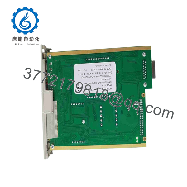
05701-A-0302
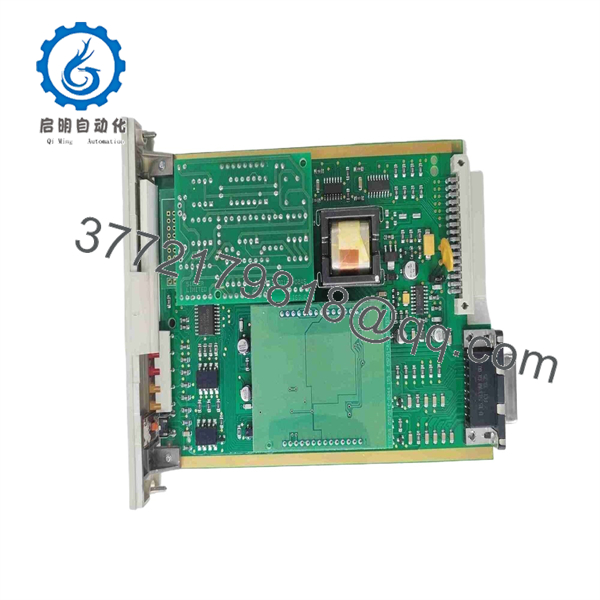
05701-A-0302
Installation & Configuration Guide
Stage 1: Pre-Installation Preparation — Allow 10 Minutes
⚠️ Safety First: Notify operations, place the gas detection system in the approved maintenance state, and follow the site’s LOTO procedure. Honeywell specifies that System 57 equipment requires qualified personnel for installation, maintenance, and calibration. The manual also states that the equipment is intended for indoor use and must not be exposed to rain or moisture.
Tools Required:
- ESD wrist strap
- PH1 screwdriver
- Calibrated digital multimeter
- Wire labels
- Smartphone or camera
- Appropriate test gas and calibration equipment where required by the site procedure
Data Backup:
- Record the existing 05701-A-0302 part number and hardware markings.
- Photograph the front panel and installed position.
- Record the associated Field Interface or Relay Card.
- Photograph all wiring before removal.
- Record Engineering Card configuration and alarm settings.
- Record any optional analogue output configuration.
- Keep the old card available until commissioning is complete.
The 5701 system stores channel configuration in EEPROM, but do not assume that every replacement card has identical configuration. Verify the actual installed channel configuration before declaring the replacement operational.
Stage 2: Removing the Old Module — Allow 5 Minutes
- Confirm the rack is de-energized and verify the DC supply with a multimeter.
- Remove the applicable front cover or card-retaining hardware.
- Do not disconnect field wiring unnecessarily. The System 57 architecture separates the Channel Control Card from the Field Interface/Relay Card.
- Release the card’s retaining screws or locking mechanism.
- Pull the control card straight out from the rack.
- Inspect the backplane connector for contamination, bent contacts, or mechanical damage.
- Place the removed card in an ESD-safe bag.
⚠️ Do not use the field wiring as a handle. The Channel Control Card connects to the rack backplane while the associated Field Interface/Relay Card handles the field-side connections.
Stage 3: Installing the New Module — Allow 5 Minutes
- Put on the grounded ESD wrist strap before handling the replacement.
- Verify that the replacement is 05701-A-0302, not the similar 05701-A-0301 4–20 mA version.
- Confirm that the catalytic sensor drive module is present and correctly fitted.
- Inspect the 14-way sensor-drive connectors and card-edge/backplane connector.
- Insert the card straight into the correct rack position.
- Secure the card using the original retaining screws.
- Confirm that the associated Field Interface/Relay Card remains correctly matched to the channel.
- Do not force the card if mechanical resistance occurs.
Self-Checklist:
- Part number reads 05701-A-0302
- Catalytic sensor drive is fitted
- Correct rack slot confirmed
- Backplane connector clean
- Card fully seated
- Retaining screws secured
- Field Interface/Relay Card unchanged
- Wiring and channel identification verified
Stage 4: Power-On & Testing — Allow 10 Minutes
- Check the 24 V DC system supply before energizing. Honeywell specifies an operating range of 18–32 V DC.
- Power the System 57 rack.
- Confirm that the front-panel display initializes.
- Check the Fault and Inhibit indications.
- Confirm the channel displays the expected gas reading.
- Use the Engineering Card to interrogate the channel.
- Verify alarm thresholds against the recorded configuration.
- Test the connected detector according to the approved calibration procedure.
- Verify A1, A2, and A3 alarm operation where applicable.
- Verify associated relay outputs and any analogue output module.
- Confirm the channel returns to its normal operating state after testing.
Honeywell’s commissioning procedure specifically calls for checking the display and the Inhibit LED after installing a control card. The manual notes that the normal startup inhibit period is typically about 30 seconds, after which the Inhibit indication should clear if the channel starts normally.
⚠️ If the Fault indication remains active, do not simply reset the card repeatedly. Check sensor wiring, the catalytic bridge condition, supply voltage, card seating, and the configuration using the Engineering Card.
Technical Replacement Traps
1. ⚠️ Wrong Card Variant
The 05701-A-0301 is the 4–20 mA version, while 05701-A-0302 is the catalytic version. They are not interchangeable merely because their mechanical format is similar.
2. ⚠️ Sensor Drive Mismatch
The 05701-A-0302 uses the 05701-A-0284 catalytic sensor drive. Do not substitute a 05701-A-0283 4–20 mA drive without confirming the complete channel architecture.
3. ⚠️ Power Budget
The catalytic control card consumes approximately 3.75 W per channel under the published test condition. Calculate total rack demand rather than sizing the supply from the card count alone.
4. ⚠️ Sensor Cable Resistance
The catalytic bridge specification limits maximum line resistance to 40 Ω at 250 mA, including the sensor. Long cable runs can therefore become a functional constraint.
5. ⚠️ Calibration Is Not Optional
A card replacement does not by itself prove that the gas detection channel is calibrated. Complete the site’s approved calibration and functional test procedure before returning the channel to service.
Frequently Asked Questions (FAQ)
1. Can the Honeywell 05701-A-0302 be hot-swapped?
Do not assume it can be hot-swapped. The System 57 documentation describes controlled installation and power-down procedures for card installation. For a field replacement, isolate the appropriate power source and follow the site’s LOTO procedure rather than removing the card under power.
2. Is the 05701-A-0302 obsolete?
Yes. Current distributor listings identify the 05701-A-0302 as discontinued/obsolete. That makes exact part-number verification important when buying surplus stock. Do not accept a different 5701 card simply because it fits the same rack.
3. Is 05701-A-0301 a direct replacement?
No. 05701-A-0301 is the 4–20 mA version, while 05701-A-0302 is the catalytic version. The associated sensor-drive architecture is different. Verify the detector type before selecting a replacement.
4. Will I lose the existing programming when I remove the card?
The 5701 Channel Control Card stores its software configuration in EEPROM, so the installed configuration should be documented before replacement rather than assumed to transfer automatically to another physical card. Record alarm settings and other channel parameters with the Engineering Card before removing the original unit.
5. What should I verify before buying a replacement?
At minimum, verify 05701-A-0302, the System 57/5701 rack type, catalytic sensor application, associated Field Interface/Relay Card, and required accessories. Ask the supplier for clear photographs of the actual nameplate and card condition if the unit is offered as surplus.
6. Can I buy a New Original or New Surplus unit?
Potentially, but condition must be confirmed for the specific physical unit. Because the model is discontinued, marketplace listings can include new surplus, unused old stock, refurbished units, or previously installed cards. Request the exact condition, photographs, serial/identification markings, and test documentation before purchase.
7. What testing should be completed after replacement?
At minimum, verify DC supply, card seating, display startup, Fault/Inhibit status, sensor response, alarm thresholds, and associated relay outputs. A gas-detection channel should also undergo the applicable calibration and functional test before being returned to service. Honeywell specifies calibration and maintenance by qualified personnel.



