
 WhatsApp: +86 16626708626
 Email:
  Phone: +86 16626708626
Description
Key Technical Specifications
| Parameter | Value |
|---|---|
| Manufacturer | Honeywell Analytics |
| Part Number | 05701-A-0327 |
| Product Family | System 57 / 5701 |
| Product Type | Double SPCO Relay Card |
| Relay Outputs | A1, A2, Fault |
| Relay Configuration | Single-Pole Changeover (SPCO) |
| Contact Type | Voltage-free relay contacts |
| Contact Rating | 5 A at 250 VAC / 32 VDC, non-inductive |
| Relay Operation | Selectable latching/non-latching |
| Relay State | Selectable normally energized/de-energized |
| Power Consumption | 0.8 W |
| Maximum Cable Size | 2.5 mm² / 14 AWG |
| Operating Temperature | −5°C to +55°C |
| Storage Temperature | −25°C to +55°C |
| Operating Humidity | 20–99% RH, non-condensing |
| Weight | Approximately 155 g |
| EMC Standard | EN 50270 |
| System | Honeywell System 57 / 5701 |
Honeywell’s System 57 documentation identifies 05701-A-0327 as the Double SPCO Relay Card for the 5701 system. It provides relay outputs associated with A1, A2, and Fault conditions.
The published technical data specifies 5 A at 250 VAC or 32 VDC for non-inductive loads, 0.8 W power consumption, selectable latching/non-latching and energized/de-energized relay operation, and terminals accepting conductors up to 2.5 mm² / 14 AWG.
Product Introduction
The Honeywell 05701-A-0327 is a Double SPCO Relay Card used in the Honeywell System 57 / 5701 gas detection control system. It provides voltage-free relay contacts for A1, A2, and Fault conditions, allowing the 5701 controller to interface with external annunciation, shutdown, alarm, or plant control circuits.
This card is selected when a 5701 channel requires discrete relay outputs rather than only the control-card functions. Relay behavior can be configured for latching/non-latching and normally energized/de-energized operation. Verify the existing relay logic before replacement because changing the energized state can alter the plant’s fail-safe behavior.
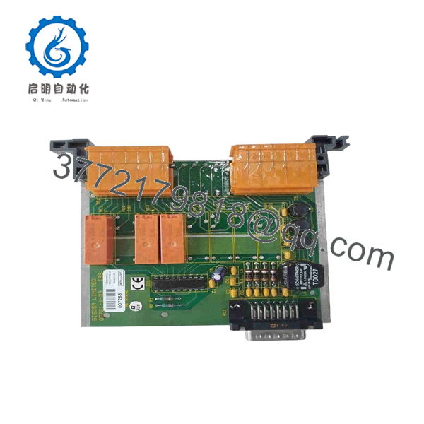
05701-A-0327

05701-A-0327
Installation & Configuration Guide
Stage 1: Pre-Installation Preparation — Allow 10 Minutes
⚠️ Safety First: Put the associated gas detection channel into the approved maintenance state. Notify operations and follow the site’s LOTO procedure before removing the relay card. Do not treat this as an ordinary PLC output module; its contacts may be connected to shutdown, alarm, or other safety-related circuits.
Tools Required:
- ESD wrist strap
- PH1 screwdriver
- Calibrated multimeter
- Wire labels
- Smartphone or camera
- Approved electrical test equipment
Data Backup:
- Record the exact part number: 05701-A-0327.
- Photograph the installed relay card and terminal wiring.
- Record which terminals correspond to A1, A2, and Fault.
- Record whether each relay is configured as energized/de-energized.
- Record whether the application uses latching or non-latching operation.
- Identify the associated 05701-A-0301 or 05701-A-0302 control card.
- Keep the removed relay card until the replacement passes functional testing.
The 5701 architecture lists 05701-A-0327 alongside the 05701-A-0326 Field Interface Card and other relay-card variants. It is important to identify the installed card rather than substituting a 05701-A-0328 or 05701-A-0329 simply because those cards belong to the same product family.
Stage 2: Removing the Old Module — Allow 5 Minutes
- De-energize the relevant System 57 equipment following the site LOTO procedure.
- Verify the absence of hazardous voltage with a calibrated multimeter.
- Photograph the complete terminal arrangement.
- Label each external conductor before disconnecting it.
- Remove the terminal connections without pulling on the conductors.
- Release the card retaining hardware.
- Withdraw the 05701-A-0327 straight from the rack.
- Inspect the connector and backplane for contamination or mechanical damage.
- Store the removed card in an ESD-safe package.
⚠️ Do not rely on wire color or memory. Relay contacts are commonly integrated into plant alarm and shutdown circuits. One misplaced common/NO/NC connection can produce an apparently healthy card with incorrect plant behavior.
Stage 3: Installing the New Module — Allow 5 Minutes
- Put on the grounded ESD wrist strap.
- Confirm the replacement marking reads 05701-A-0327.
- Compare the replacement card against the original before installation.
- Confirm the relay configuration required by the existing system.
- Insert the card into the correct System 57 position.
- Ensure the card seats fully without excessive force.
- Secure the card using the appropriate retaining hardware.
- Reconnect each conductor according to the photograph and wiring documentation.
- Check each relay’s common, normally open, and normally closed connections.
- Tighten terminals appropriately for the installed terminal hardware.
Self-Checklist:
- Part number is 05701-A-0327
- Correct System 57 slot confirmed
- A1 wiring verified
- A2 wiring verified
- Fault wiring verified
- Common/NO/NC contacts verified
- Relay energized/de-energized logic verified
- Latching/non-latching configuration verified
- Terminal connections secured
Stage 4: Power-On & Testing — Allow 10 Minutes
- Check the DC supply and adjacent System 57 circuitry before energizing.
- Restore power according to the approved startup procedure.
- Confirm the associated 5701 control card initializes normally.
- Verify that no unexpected Fault condition appears.
- Initiate an approved A1 alarm test.
- Confirm the A1 relay changes state at the external terminals.
- Repeat the test for A2.
- Perform an approved Fault-condition test.
- Verify the plant DCS/PLC or annunciator receives the expected discrete status.
- Return the channel to normal operation and confirm all alarms clear correctly.
Honeywell specifies that the 05701-A-0327 relay card provides A1, A2, and Fault single-pole changeover relay functions.
⚠️ Do not stop at checking the relay-card contacts with an ohmmeter. The important test is the complete signal path: gas detection controller → relay card → plant termination → DCS/PLC/annunciator → operator indication or shutdown logic.
Technical Replacement Traps
1. ⚠️ Confusing 05701-A-0327 With 05701-A-0328
Both are 5701 relay cards, but their relay configurations differ. 05701-A-0327 provides A1, A2, and Fault, while 05701-A-0328 adds A3 and Inhibit functions.
2. ⚠️ Changing Relay Fail-Safe Logic
The relay operation can be configured as normally energized or normally de-energized. Do not assume the replacement should use the factory/default state. Match the site’s documented fail-safe philosophy.
3. ⚠️ Ignoring NO/NC Contact Selection
A relay card can appear to operate correctly while the external circuit is wired to the wrong contact. Verify the actual contact transition during an A1, A2, and Fault test.
4. ⚠️ Using the Wrong Cable Size or Terminal Method
The published specification permits cable up to 2.5 mm² / 14 AWG. Confirm the actual terminal arrangement and conductor requirements before installation.
5. ⚠️ Testing Only the Card
I’ve seen replacement work declared complete because the relay clicked during a bench test. That proves very little. For a gas detection system, verify the complete downstream alarm path before returning the channel to service.
Frequently Asked Questions (FAQ)
1. What is the Honeywell 05701-A-0327 used for?
It is a Double SPCO Relay Card for the Honeywell System 57 / 5701. It provides A1, A2, and Fault relay outputs for interfacing the gas detection system with external alarm, control, or shutdown circuits.
2. Is 05701-A-0327 the same as 05701-A-0328?
No. The 05701-A-0327 provides A1, A2, and Fault relay functions. The 05701-A-0328 is a Triple SPCO version that also handles A3 and Inhibit. Select the replacement based on the installed system’s actual relay requirements.
3. What is the contact rating of the 05701-A-0327?
The published specification is 5 A at 250 VAC / 32 VDC for non-inductive loads. Do not interpret that rating as permission to switch any arbitrary motor, solenoid, or inductive load directly. Check the load characteristics and the site’s electrical design.
4. Is Honeywell 05701-A-0327 obsolete?
The model is a legacy System 57 component, and distributor listings identify it as discontinued. Honeywell’s current product documentation still lists the part as a System 57 spare/accessory. Because availability varies, verify the physical unit and its condition before ordering.
5. Can I replace 05701-A-0327 without changing the control card?
Normally, the relay card is a separate System 57 component and is designed to interface with the associated 5701 control architecture. However, verify the existing rack, control card, Field Interface arrangement, wiring, and relay logic before replacement. Honeywell’s system documentation explicitly shows 05701-A-0327 as a separate relay/interface component.
6. Is a New Surplus 05701-A-0327 the same as refurbished?
No. New Surplus normally means unused OEM stock that has entered secondary inventory, while Refurbished means a previously used unit that has undergone inspection and testing. Ask for the exact physical condition, label photographs, serial/identification information, and test evidence before purchasing.
7. What should I request from a supplier before buying?
For a discontinued 05701-A-0327, request the exact part-number photograph, revision/issue information where applicable, physical-condition statement, and available functional-test documentation. If the application controls a gas detection or shutdown circuit, also confirm that the seller has tested the A1, A2, and Fault relay functions, not merely powered the card.



