
 WhatsApp: +86 16626708626
 Email:
  Phone: +86 16626708626
Description
Key Technical Specifications
| Parameter | Value |
|---|---|
| Manufacturer | Honeywell Analytics |
| Part Number | 05704-A-0144 |
| Product Family | System 57 / 5704 |
| Product Type | Four-Channel Control Card |
| Input Type | Catalytic bridge |
| Number of Channels | 4 |
| Supply Voltage | 18–32 V DC |
| Catalytic Drive Method | Constant current |
| Catalytic Drive Current | 90–315 mA, electronically adjustable |
| Maximum Drive Voltage | 10 V |
| Full-Scale Signal Range | 15–300 mV |
| Maximum Line Resistance | 40 Ω at 250 mA, including sensor |
| Typical Power Consumption | 8.5 W |
| Maximum Power Consumption | 12.8 W at 200 mA sensor current |
| Display | Backlit LCD; bar graph, peak reading, digital and alphanumeric |
| Channel Indicators | A1, A2, A3, Fault, Inhibit for each channel |
| Remote Functions | Inhibit and remote alarm reset |
| Initial Accuracy | ±1% |
| Linearity | 2% FSD |
| Repeatability | 2% FSD |
| Electronic Drift | <3% over 6 months |
| Operating Temperature | −5°C to +55°C |
| Storage Temperature | −25°C to +55°C |
| Operating Humidity | 20–90% RH, non-condensing |
| Dimensions | 3U high × 25 mm wide |
| Weight | Approximately 165 g |
| EMC | EN 50270 |
Honeywell’s System 57 product documentation lists 05704-A-0144 specifically as the 4-Channel Control Card for catalytic input, while 05704-A-0145 is the corresponding 4–20 mA version.
The published technical data specifies an 18–32 V DC supply, constant-current catalytic bridge drive adjustable from 90 to 315 mA, 15–300 mV full-scale signal range, and a maximum 40 Ω line resistance at 250 mA including the sensor.
Product Introduction
The Honeywell 05704-A-0144 is a four-channel control card for the System 5704 gas detection system, designed specifically for catalytic bridge-type gas detectors. One card provides control, display, sensor excitation, alarm evaluation, and status indication for four connected detector channels.
The card uses a backlit LCD and individual channel indicators for A1, A2, A3, Fault, and Inhibit conditions. Its software configuration is stored in EEPROM. Do not substitute the visually similar 05704-A-0145, because that card is designed for 4–20 mA inputs rather than catalytic bridge sensors.
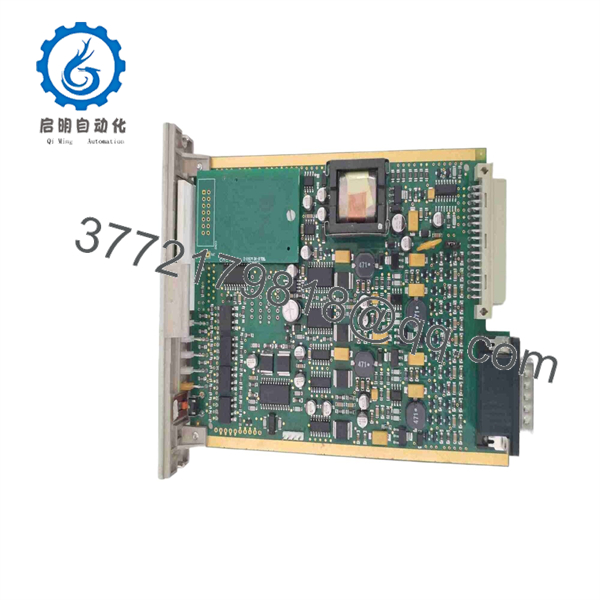
05704-A-0144
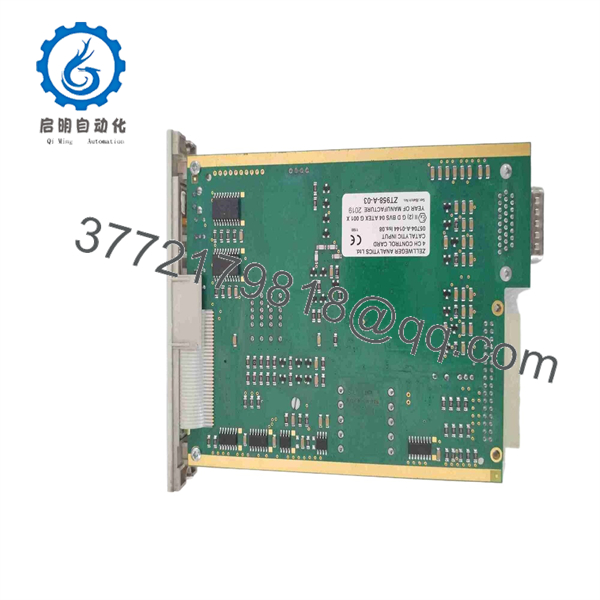
05704-A-0144
Installation & Configuration Guide
Stage 1: Pre-Installation Preparation — Allow 10 Minutes
⚠️ Safety First: Place the affected gas detection channels into the site’s approved maintenance state. Notify operations, isolate the System 5704 supply under the applicable LOTO procedure, and verify that the rack is de-energized before removing the card.
Tools Required:
- ESD wrist strap
- PH1 screwdriver
- Calibrated multimeter
- Wire labels
- Smartphone or camera
- Approved gas calibration equipment where required
Data Backup:
- Record the exact part number: 05704-A-0144.
- Photograph the front-panel display and all four channel positions.
- Record each channel’s detector type and measurement range.
- Record A1, A2, and A3 alarm settings.
- Record Fault and Inhibit behavior.
- Photograph the rear/backplane connections.
- Record any installed analogue output modules.
- Record the existing firmware/configuration information where accessible.
Honeywell documentation states that the 5704 control card’s software configuration is stored in EEPROM. Do not assume a replacement card has identical configuration simply because the part number matches.
Stage 2: Removing the Old Module — Allow 5 Minutes
- Verify that the System 5704 rack is de-energized.
- Use a multimeter to confirm the expected DC supply is absent.
- Remove the appropriate front retaining hardware.
- Photograph the card and connector positions.
- Disconnect associated wiring or interface connections as required.
- Release the card retaining mechanism.
- Pull the card straight out of the rack.
- Inspect the backplane connector for bent contacts, contamination, or mechanical damage.
- Place the removed card in an ESD-safe bag.
⚠️ Keep the original card until commissioning is complete. Its configuration and hardware markings may be needed if the replacement does not reproduce the existing channel behavior.
Stage 3: Installing the New Module — Allow 5 Minutes
- Ground yourself with the ESD strap.
- Verify that the replacement is marked 05704-A-0144.
- Confirm that the application uses catalytic bridge sensors.
- Verify that the replacement is not the 05704-A-0145 4–20 mA version.
- Check the card connector and backplane for damage.
- Insert the card straight into the correct System 5704 position.
- Ensure it is fully seated.
- Secure the card using the original retaining hardware.
- Verify any analogue output modules are fitted in the correct channel positions.
- Restore associated interface connections.
Self-Checklist:
- 05704-A-0144 confirmed
- Catalytic input confirmed
- Four channel positions verified
- Backplane connector inspected
- Card fully seated
- Retaining hardware secured
- Analogue output modules checked
- Existing configuration documented
Stage 4: Power-On & Testing — Allow 10–15 Minutes
- Measure the DC supply before powering the rack.
- Confirm the supply is within the specified 18–32 V DC range.
- Energize the System 5704 rack.
- Observe the green power indication.
- Confirm the LCD initializes correctly.
- Check CH1 through CH4 status indications.
- Check for unexpected Fault or Inhibit indications.
- Select each channel and verify the displayed gas reading.
- Confirm the configured alarm thresholds.
- Perform an approved detector response/calibration test.
- Test A1, A2, and A3 alarm functions as required.
- Verify Fault and Inhibit behavior.
- Confirm any analogue output modules produce the expected signal.
The card provides individual A1, A2, A3, Fault, and Inhibit indications for each channel, while the front-panel push button provides alarm reset and card-selection functions for Engineering Card access.
⚠️ Do not return a gas detection channel to service solely because the LCD displays a gas concentration. Verify detector response, alarm thresholds, fault monitoring, and downstream relay/interface behavior.
Technical Replacement Traps
1. ⚠️ Do Not Substitute the 4–20 mA Card
The 05704-A-0144 is the catalytic-input version. The 05704-A-0145 is designed for 4–20 mA inputs. They are different control-card variants despite sharing the same System 5704 platform.
2. ⚠️ Check Catalytic Drive Current
The card’s catalytic bridge drive is electronically adjustable from 90 to 315 mA. The correct current depends on the detector and application. Do not copy an arbitrary value from another channel.
3. ⚠️ Watch Cable Resistance
The published limit is 40 Ω at 250 mA, including the sensor. Long cable runs can therefore affect the detector circuit and should be checked when troubleshooting abnormal readings.
4. ⚠️ Do Not Ignore EEPROM Configuration
The control card stores its software configuration in EEPROM. Document the old card’s configuration before removal rather than assuming the replacement will automatically match the existing system.
5. ⚠️ Test All Four Channels
A replacement can pass a basic power-up test while one channel remains incorrectly configured. Test CH1, CH2, CH3, and CH4 individually, including their alarm and fault behavior.
Frequently Asked Questions (FAQ)
1. What is Honeywell 05704-A-0144 used for?
The 05704-A-0144 is a four-channel catalytic control card for the Honeywell System 5704 gas detection system. It provides control, sensor excitation, display, alarm processing, and channel status functions for four catalytic gas detector inputs.
2. What is the difference between 05704-A-0144 and 05704-A-0145?
The key difference is the input technology. 05704-A-0144 is for catalytic bridge inputs, while 05704-A-0145 is for 4–20 mA inputs. They should not be treated as interchangeable replacement cards.
3. Can 05704-A-0144 be hot-swapped?
Do not assume hot-swapping is permitted. For a field replacement, de-energize the applicable System 5704 equipment under the site’s LOTO procedure before removing the control card. This is particularly important because the card interfaces with gas detection and alarm functions.
4. What supply voltage does the 05704-A-0144 require?
The published specification is 18–32 V DC. Power consumption is approximately 8.5 W typical for the catalytic configuration, with published maximum consumption of 12.8 W under the specified sensor-current condition.
5. Is 05704-A-0144 obsolete?
Yes. It is a legacy/discontinued System 5704 component. Current secondary-market listings identify the manufacturer status as discontinued, although new-surplus and previously used units may still be available.
6. Does replacing the card erase the gas detector configuration?
The 5704 control card stores its software configuration in EEPROM. However, you should not assume that a replacement card contains the configuration required by your particular installation. Record the existing configuration and verify every channel after replacement.
7. What condition should I request when buying a replacement?
For a legacy safety-related control card, specify the condition explicitly: New Original/New Surplus or Refurbished and Tested. Ask for photographs of the actual 05704-A-0144, its identification label, revision/issue marking, and available test documentation. Current market listings demonstrate that both unused and refurbished units are offered.



