
 WhatsApp: +86 16626708626
 Email:
  Phone: +86 16626708626
Description
Key Technical Specifications
| Parameter | Value |
|---|---|
| Model | 51196653-100 |
| Manufacturer | Honeywell |
| Product Type | TDC 3000 five-slot file power supply |
| System | Honeywell TDC 3000 / LCN |
| Input Voltage | 102–264 VAC RMS, auto-ranging |
| Input Frequency | 47–63 Hz |
| Input Rating | 120 VAC at 6 A / 240 VAC at 3 A* |
| DC Output 1 | +5 VDC, up to 30 A* |
| DC Output 2 | +12 VDC, up to 10 A* |
| DC Output 3 | −12 VDC, up to 1 A* |
| DC Output 4 | +27 VDC, up to 1.2 A* |
| Power Factor Correction | Yes |
| Connector | Standard 3-pin connector |
| Chassis Application | Five-slot chassis |
| Compliance | CE-compliant |
| Cooling | Temperature and +5 V output-load controlled fan |
| Clock Configuration | Internal line-frequency clock by default; PCB jumper supports external clock configuration |
| Net Weight | Approximately 8.19 lb / 3.71 kg |
The 51196653-100 is identified across multiple industrial automation sources as a Honeywell TDC 3000 five-slot power supply. The 102–264 VAC auto-ranging input, CE compliance, PFC, controlled cooling fan, and 3-pin connector are specifically documented by a Honeywell DCS specialist.
The individual output-current figures are published by third-party inventory sources and should be checked against the installed unit’s documentation before loading the supply near its limits.
Product Introduction
The Honeywell 51196653-100 is a CE-compliant five-slot power supply for Honeywell TDC 3000 control-system chassis. It provides the multiple DC rails required by the modular chassis and uses an auto-ranging 102–264 VAC input.
One important replacement detail is the connector arrangement. The 51196653-100 uses a standard 3-pin connector and may require a replacement cable when installed with an original five-slot chassis using the older 8-pin power connector.
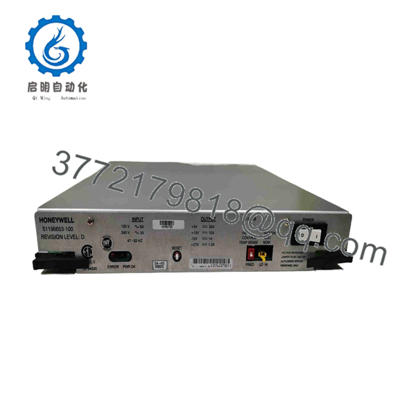
51196653-100
Installation & Configuration Guide
Stage 1: Pre-Installation Preparation — Approx. 10–15 Minutes
⚠️ Safety First
- Notify operations and obtain authorization for the TDC 3000 chassis shutdown.
- Put the process into its approved safe state.
- Apply lockout/tagout to the applicable AC supply.
- Verify that the chassis is de-energized.
- Allow the equipment’s capacitors to discharge for at least 5 minutes, or follow the applicable Honeywell maintenance procedure if it specifies a longer interval.
- Verify the absence of hazardous voltage with a properly rated multimeter.
Tools Required
- ESD wrist strap
- Digital multimeter
- Appropriate screwdriver
- Wire labels
- Smartphone/camera
- Insulated tools suitable for the cabinet
Data Backup
- Record the complete 51196653-100 part number.
- Photograph the existing power-supply connector.
- Photograph cable routing and chassis connections.
- Record whether the chassis uses the newer 3-pin connection or an older 8-pin arrangement.
- Check the PCB clock jumper configuration if the installed application uses Sequence of Events (SOE).
- Record the existing TDC 3000 chassis configuration before removal.
⚠️ Do not assume that every five-slot chassis has the same connector arrangement. Honeywell’s 51196653-100 documentation specifically notes compatibility considerations between the standard 3-pin connector and an original chassis using an 8-pin power connector.
Stage 2: Removing the Old Module — Approx. 5–10 Minutes
- Remove the chassis cover or access panel as required.
- Confirm the AC supply is isolated.
- Verify zero hazardous voltage before touching the power supply.
- Photograph the connector and cable arrangement.
- Label the power connections.
- Disconnect the connector using its locking mechanism.
- Release the power-supply retaining hardware.
- Remove the power supply without forcing it against the chassis.
- Inspect the mating connector for discoloration, damaged contacts, loose pins, or signs of overheating.
⚠️ Keep the removed power supply until the replacement has completed load and system testing. The old unit is also your best reference for connector and jumper configuration.
Stage 3: Installing the New Module — Approx. 5–10 Minutes
- Attach the grounded ESD wrist strap.
- Verify the replacement marking reads 51196653-100.
- Compare the connector arrangement with the original unit.
- Confirm the replacement cable requirement if the chassis has the older 8-pin connection.
- Inspect the PCB and connectors for shipping damage.
- Position the power supply correctly in the five-slot chassis.
- Secure the retaining hardware.
- Reconnect the power connector.
- Verify that the connector is completely seated.
- Check the clock jumper configuration against the original unit and system requirements.
Clock Configuration
The 51196653-100 is normally pinned for the internal line-frequency clock. For an installation requiring external clock synchronization for SOE, the PCB jumper configuration must be checked against the system architecture.
Self-Checklist
- 51196653-100 verified
- Chassis compatibility verified
- Connector type verified
- Replacement cable checked
- Power wiring secured
- Clock jumper checked
- Mounting hardware secured
- No loose hardware inside chassis
Stage 4: Power-On & Testing — Approx. 10–20 Minutes
Pre-Power Check
- Inspect the chassis for loose screws or conductive debris.
- Verify protective earth continuity.
- Confirm the AC input wiring.
- Check the connector for signs of arcing or overheating.
- Confirm the replacement supply is mechanically secure.
Power-On Steps
- Energize the chassis according to the approved Honeywell startup procedure.
- Observe the power-supply status indications.
- Check the TDC 3000 chassis for abnormal alarms.
- Verify that the installed modules receive their required supply rails.
- Check controller and I/O diagnostics.
- Monitor the power supply during initial operation.
- Run the system through a controlled functional test.
- Check for abnormal fan behavior or thermal rise.
- Confirm that the control system remains stable under normal module loading.
⚠️ Do not immediately return the process to full production if the supply powers up but downstream modules report faults. Check the DC rails, connector arrangement, chassis compatibility, and power loading first.
Technical Pitfalls
❗ Connector-generation mismatch: This is one of the most important issues with this part. The 51196653-100 has a standard 3-pin connector, while some original five-slot chassis use an 8-pin power connector and require a replacement cable.
❗ SOE clock configuration: The supply is normally configured for the internal line-frequency clock. If the node participates in an external-clock SOE architecture, verify the PCB jumper configuration before commissioning.
❗ Input-voltage assumption: The supply is auto-ranging over approximately 102–264 VAC RMS according to specialist documentation. Still, verify the actual cabinet supply and wiring before energizing the unit.
❗ Power loading: A five-slot supply may feed several installed modules simultaneously. Do not judge loading from the number of occupied slots alone; calculate the actual DC rail demand.
❗ Legacy-system condition: A replacement power supply cannot compensate for damaged backplane connectors, degraded wiring, or other aging TDC 3000 hardware. Inspect the mating chassis before installation.
Frequently Asked Questions (FAQ)
Q1. What is Honeywell 51196653-100?
The 51196653-100 is a Honeywell TDC 3000 five-slot file power supply used to provide power to modular control-system hardware. It is also listed as a chassis power supply and CE-compliant five-slot supply.
Q2. What are the outputs of the 51196653-100?
Third-party technical listings identify four primary DC rails: +5 VDC, +12 VDC, −12 VDC, and +27 VDC, with published maximum currents of approximately 30 A, 10 A, 1 A, and 1.2 A respectively. Verify these ratings against the applicable Honeywell documentation before designing around the supply’s maximum load.
Q3. Can I directly install 51196653-100 into an older five-slot chassis?
Not necessarily. The 51196653-100 uses a standard 3-pin connector, while an original five-slot chassis may have an 8-pin power connector. In that case, Honeywell-system documentation indicates that a replacement cable is required.
Q4. Does 51196653-100 support Sequence of Events?
The power supply participates in the system clock arrangement. The unit is normally configured for an internal line-frequency clock, while a PCB jumper allows configuration for an external clock when required by an SOE architecture. Verify the clock-master/slave design before changing the jumper.
Q5. Is Honeywell 51196653-100 obsolete?
It belongs to the legacy TDC 3000 generation, and current public listings are primarily industrial spare-parts listings rather than a current Honeywell product catalog. That makes lifecycle verification important before planning a long-term replacement strategy. Do not assume a third-party “in stock” listing means Honeywell still manufactures the unit.
Q6. Can I hot-swap the 51196653-100?
Do not assume it is hot-swappable. This is an AC-input chassis power supply, and the replacement procedure should be performed with the applicable power isolated unless the exact Honeywell system documentation explicitly permits live replacement.
Q7. Why do suppliers list different conditions for 51196653-100?
Because this is a legacy industrial spare, inventory can include factory-sealed surplus, new old stock, tested/refurbished units, and repaired units. Some suppliers advertise brand-new stock while others explicitly sell tested or refurbished equipment.
For procurement, specify the required condition in the purchase order. If the application is production-critical, request photographs of the actual 51196653-100 nameplate, connector, PCB revision, and packaging before shipment.



