
 WhatsApp: +86 16626708626
 Email:
  Phone: +86 16626708626
Description
Key Technical Specifications
| Parameter | Value |
|---|---|
| Model / Part Number | 51199929-100 |
| Manufacturer | Honeywell |
| Product Family | TDC 3000 |
| Product Type | System power supply |
| Application | Honeywell TDC 3000 control-system hardware |
| Input Voltage | Verify from unit nameplate |
| Input Frequency | Verify from unit documentation |
| DC Output Rails | Verify exact revision before installation |
| Output Current | Verify exact revision before installation |
| Connector Type | Verify against existing chassis |
| Cooling Method | Verify from installed-unit documentation |
| Mounting | TDC 3000 system/chassis installation |
| Operating Temperature | Verify from OEM documentation |
| Dimensions | Verify from OEM documentation |
| Weight | Verify from actual unit/revision |
Engineering note: I would not publish unverified voltage, current, connector, temperature, or dimensional data for 51199929-100. Legacy Honeywell TDC 3000 power supplies can look similar while having different electrical and mechanical interfaces. The exact suffix and hardware revision need to match.
Product Introduction
The Honeywell 51199929-100 is a legacy TDC 3000 system spare associated with Honeywell process-control hardware. Available public information is insufficient to establish a complete OEM electrical specification, so the installed-unit nameplate and applicable TDC 3000 documentation should control any replacement decision.
For maintenance procurement, verify the complete 51199929-100 part number, PCB revision, connector arrangement, chassis location, and input/output ratings. Do not assume that specifications from another Honeywell TDC 3000 power-supply part number apply to this unit.
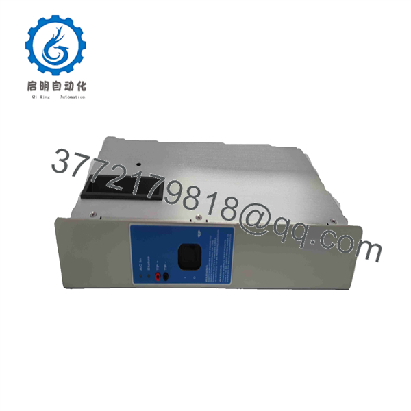
51199929-100
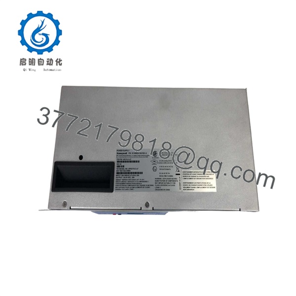
51199929-100
Installation & Configuration Guide
Stage 1: Pre-Installation Preparation — Approx. 10–15 Minutes
⚠️ Safety First
- Notify operations and obtain authorization for the shutdown.
- Place the controlled process in its approved safe state.
- Apply the site’s lockout/tagout procedure.
- Isolate the relevant AC supply.
- Allow the equipment to discharge for at least 5 minutes, or follow the specific Honeywell maintenance procedure if it specifies a longer period.
- Verify the absence of hazardous voltage with a properly rated multimeter.
Tools Required
- ESD wrist strap
- Digital multimeter
- Appropriate screwdriver
- Wire labels
- Smartphone/camera
- Torque-controlled screwdriver where required
Data Backup
- Record the complete 51199929-100 part number.
- Photograph the installed power supply from the front and rear.
- Photograph every connector before removal.
- Record PCB revision and serial information.
- Photograph any jumpers, DIP switches, or configuration links.
- Record the host chassis/file number.
- Document the existing power-distribution arrangement.
⚠️ Do not order or install this unit based only on the description “TDC 3000 power supply.” Verify the exact part number and hardware revision.
Stage 2: Removing the Old Module — Approx. 5–10 Minutes
- Remove the chassis cover or access panel according to the applicable Honeywell procedure.
- Confirm that the AC supply is isolated.
- Verify zero hazardous voltage before touching the power supply.
- Photograph the complete connector arrangement.
- Label each cable.
- Disconnect the power connectors using their locking mechanisms.
- Remove the retaining screws or clips.
- Withdraw the module carefully.
- Inspect the chassis connector and mating contacts for overheating, corrosion, or mechanical damage.
⚠️ Keep the original 51199929-100 until the replacement has passed commissioning. The old unit provides the most reliable reference for physical configuration.
Stage 3: Installing the New Module — Approx. 5–10 Minutes
- Put on the grounded ESD wrist strap.
- Verify that the replacement label reads 51199929-100.
- Compare the replacement and original units side by side.
- Check:
- Complete part number
- Hardware/PCB revision
- Connector locations
- Connector keying
- Mounting-hole pattern
- Jumper configuration
- Chassis compatibility
- Install the unit in the correct chassis position.
- Secure the retaining hardware.
- Reconnect every cable according to the photographs and labels.
- Confirm each connector is fully seated.
- Check that no cable is under mechanical strain.
Self-Checklist
- Part number matched
- Revision checked
- Chassis compatibility verified
- Connector arrangement matched
- Configuration copied
- Mounting secured
- Wiring secured
Stage 4: Power-On & Testing — Approx. 10–20 Minutes
Pre-Power Check
- Inspect the chassis for loose screws and conductive debris.
- Check protective-earth continuity.
- Verify incoming supply wiring.
- Inspect connectors for signs of arcing or overheating.
- Confirm the module is mechanically secured.
Power-On Steps
- Energize the system according to the approved Honeywell startup procedure.
- Observe power-supply indicators.
- Check the TDC 3000 chassis for abnormal alarms.
- Verify that downstream controller and I/O hardware powers up correctly.
- Check system diagnostics.
- Monitor the supply during initial operation.
- Confirm stable operation under the normal installed load.
- Run a controlled functional test before returning the process to normal operation.
⚠️ If downstream modules fail after the supply starts, do not immediately replace those modules. First check supply rails, connector seating, chassis compatibility, and the replacement unit’s exact electrical specification.
Technical Pitfalls
❗ Part-number confusion: Honeywell has many legacy TDC 3000 power-supply assemblies with similar physical descriptions. Never substitute a 51196653-series specification for 51199929-100 without documentation.
❗ Connector mismatch: A mechanically similar connector does not guarantee identical pin assignments. Compare the original unit and wiring documentation.
❗ Power-rail mismatch: Confirm every required DC rail before connecting the replacement. A supply that physically fits can still be electrically wrong.
❗ Hardware revision: Record the PCB revision before removal. Revision differences can matter when maintaining legacy control-system hardware.
❗ ESD: Handle the PCB by its edges and use a grounded wrist strap. Avoid touching exposed components or connector contacts.
Frequently Asked Questions (FAQ)
Q1. What is Honeywell 51199929-100?
The 51199929-100 is a Honeywell legacy control-system spare associated with the TDC 3000 platform. Public technical information for this exact part number is limited, so its precise electrical function should be confirmed from the installed equipment and OEM documentation.
Q2. Is 51199929-100 a power supply?
It is commonly identified in industrial spare-parts contexts as a TDC 3000 power-related assembly, but I would not publish a definitive voltage or current specification without the applicable Honeywell documentation. Confirm the nameplate and chassis application before purchasing.
Q3. Can I replace 51199929-100 with another Honeywell TDC 3000 power supply?
Not automatically. Compare the input rating, DC output rails, current capacity, connector pinout, mounting arrangement, chassis compatibility, and hardware revision. Similar appearance is not sufficient evidence of interchangeability.
Q4. Can I hot-swap 51199929-100?
Do not assume it is hot-swappable. Unless the specific TDC 3000 equipment documentation explicitly permits live replacement, isolate the applicable power source and follow the approved maintenance procedure.
Q5. Will replacing 51199929-100 erase my TDC 3000 configuration?
The answer depends on the architecture of the particular TDC 3000 equipment. A power-supply replacement normally should not be treated as a controller-configuration replacement, but you should still document the system configuration before maintenance and verify all downstream hardware after power restoration.
Q6. Is Honeywell 51199929-100 obsolete?
It is associated with the legacy TDC 3000 generation, but I cannot verify an official Honeywell lifecycle statement for this exact part number from the available public information. Treat it as a legacy spare and confirm current OEM support before using it in a long-term maintenance plan.
Q7. What should I provide when ordering a replacement?
Provide the complete 51199929-100 marking, photographs of the actual unit, PCB/revision markings, connector arrangement, host chassis model, and any Honeywell documentation identifying the assembly. For a critical DCS application, also specify whether you require Factory Sealed, New Original/New Surplus, or Refurbished and Tested condition.



