
 WhatsApp: +86 16626708626
 Email:
  Phone: +86 16626708626
Description
Key Technical Specifications
- Manufacturer: Honeywell
- Part Number: 51301874-100
- Product Type: Thermocouple multiplexer board / thermocouple mux logic board / process I/O relay board
- System Family: Honeywell TDC 2000
- Associated Assembly: Low Energy PIU
- Primary Function: Switches and multiplexes low-level thermocouple measurement signals
- Switching Components: Reed relays
- Listed Channel Capacity: Up to 16 thermocouple inputs
- Supported Signal Class: Low-level thermocouple and millivolt measurement signals
- Typical Field Use: Temperature acquisition from direct thermocouple circuits in legacy process-control installations
- I/O Classification: Low-level analog input signal routing; not a standard 4–20 mA analog-input module
- Field Wiring Requirement: Verify thermocouple type, polarity, extension wire alloy, shield arrangement, and cold-junction compensation architecture
- Connector Requirement: Match board-side ribbon connectors, pin orientation, and PIU backplane or interface assembly
- Replacement Requirement: Match exact part number 51301874-100, installed board revision, relay arrangement, and Low Energy PIU configuration
Multiple supplier records identify 51301874-100 as a Honeywell thermocouple multiplexer board for the Low Energy PIU, containing reed relays that can switch up to 16 thermocouple inputs. It is associated with Honeywell TDC 2000 legacy process control.
Product Introduction
The Honeywell 51301874-100 is a thermocouple multiplexer logic board used with the Low Energy PIU in Honeywell TDC 2000 process-control systems. The board uses reed relays to select and route low-level thermocouple signals for temperature measurement and process monitoring. It is intended for microvolt-level sensor circuits, not general-purpose digital I/O or standard high-level analog loops.
Plants maintain this board because direct thermocouple signals are sensitive to noise, polarity errors, poor extension wiring, and contact resistance. An exact 51301874-100 replacement preserves the installed PIU architecture, but technicians must verify the board revision, relay condition, ribbon-cable orientation, thermocouple wiring, and system configuration before commissioning.
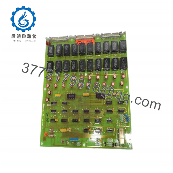
51301874-100
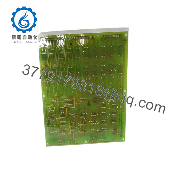
51301874-100
Troubleshooting Quick Reference
| Symptom | Possible Cause | Relevance to This Part | Quick Check Method | Recommendation |
|---|---|---|---|---|
| One temperature point reads open circuit | Open thermocouple, broken extension wire, loose terminal, failed mux relay contact | ⚠️ Medium | Isolate under the approved procedure; measure continuity from the field terminal through the extension circuit and compare sensor resistance with a known-good loop | Check sensor and field wiring before replacing the mux board |
| One temperature point reads far too high or low | Reversed thermocouple polarity, wrong extension-wire alloy, loose terminal, incorrect thermocouple type, relay contact resistance | ⚠️ Medium | Verify positive and negative conductor identification, confirm configured thermocouple type, and compare the input with a calibrated thermocouple simulator | Correct field wiring and configuration before replacing the board |
| Several temperature channels drift together | Common reference issue, cold-junction compensation issue, PIU fault, cabinet temperature change, damaged ribbon cable | ✅ High | Compare affected channels with a calibrated simulator at the board input; check PIU diagnostics, ambient temperature, and ribbon-cable seating | Inspect the board interface and common system elements before replacement |
| One channel stays fixed despite process change | Stuck reed relay, failed sensor, open signal path, controller scan/configuration issue | ✅ High | Apply a controlled simulated millivolt signal, then observe whether the value changes through the normal scan cycle | Replace the board only after simulator testing confirms the signal reaches the board |
| All low-level temperature points fail | PIU power loss, ribbon cable disconnected, controller interface fault, board failure | ⚠️ Medium | Check PIU supply rails, rack diagnostics, ribbon connectors, and system alarm logs before testing individual channels | Diagnose power and interface faults before replacing the mux board |
| Readings become noisy when nearby motors start | Shielding fault, ground loop, poor thermocouple extension cable, cable routed beside high-current conductors | ❌ Usually Low | Inspect shield termination and routing; compare signal stability with VFDs or motor starters off and on | Correct cable routing and grounding before replacing electronics |
| Incorrect values appear after board replacement | Ribbon cable reversed, incorrect connector position, wrong board revision, jumper mismatch, damaged connector pin | ✅ High | Compare old and replacement boards side by side; verify connector orientation, keying, labels, jumpers, and all visible hardware differences | Power down and correct the installation before further testing |
| Board has visible corrosion or relay damage | Cabinet contamination, moisture, chemical exposure, component aging | ✅ High | Inspect under good lighting for corrosion, residue, cracked relay packages, damaged traces, or rework marks | Remove from service and replace after identifying the contamination source |
Field warning: A thermocouple mux board can look guilty when the real problem is the thermocouple circuit. Open junctions, loose terminal screws, incorrect extension cable, reversed polarity, and wrong sensor type cause more temperature failures than the board itself. Use a calibrated thermocouple simulator at the board input before replacing hardware.
❗ Do not substitute a 4–20 mA test method: This is a low-level thermocouple multiplexer board. A standard 4–20 mA loop calibrator is not the correct diagnostic tool for confirming thermocouple input performance. Use an appropriate thermocouple or millivolt simulator with the correct sensor type and temperature reference.
❗ Thermocouple polarity is easy to get wrong: Take a photo of every field terminal before disconnection. Thermocouple extension conductors use alloy-specific color codes and polarity conventions. Do not assume a wire color or terminal label is correct without checking the approved loop drawing and installed cable specification.
❗ Reed-relay contact issues: The board uses reed relays to switch thermocouple signals. A relay contact can develop intermittent resistance or fail to close consistently, especially in older equipment exposed to vibration, moisture, contamination, or long service life. Compare the affected channel with a calibrated simulator and a known-good channel before replacing the board.
❗ Ribbon-cable orientation: Photograph every ribbon-cable connector before removal. Verify connector keying, pin-1 orientation, cable routing, and strain relief. A reversed or offset ribbon connection can create multiple false temperature readings and can waste hours of troubleshooting.
❗ ESD precautions: Wear a grounded wrist strap and work on an ESD-safe surface. Low-level analog circuitry is not forgiving. I have seen a technician handle a thermocouple interface board without a strap, reinstall it, and then chase unstable readings that were not present before the maintenance work.
Keep these checks in mind and you will save yourself 90% of typical rework time. If you are stuck, send technical support photos of the board labels, ribbon connectors, affected terminals, configured thermocouple type, diagnostics, and measured simulator results.
Frequently Asked Questions
What is Honeywell 51301874-100?
Honeywell 51301874-100 is a thermocouple multiplexer logic board for the Low Energy PIU used in Honeywell TDC 2000 process-control systems. It uses reed relays to switch and route low-level thermocouple signals for temperature measurement.
How many thermocouple channels can the 51301874-100 handle?
Supplier documentation states that the board contains reed relays capable of switching up to 16 thermocouple inputs. Confirm the active channel count, installed PIU configuration, and controller database assignment in the actual system before purchasing or commissioning a replacement.
Can I use this board for 4–20 mA pressure or flow transmitters?
No. To be honest, this board is the wrong tool for a standard 4–20 mA loop. It is designed for low-level thermocouple or millivolt signals associated with the Low Energy PIU. A 4–20 mA transmitter requires the correct high-level analog-input interface and appropriate burden or shunt arrangement.
Does this board work with Honeywell Experion C300 hardware?
Do not assume it does. The available reliable listings associate 51301874-100 with the legacy Honeywell TDC 2000 Low Energy PIU environment. Claims that it is a C300 module are inconsistent with the thermocouple mux-board descriptions and should not be used to approve a replacement.
Can I hot-swap the 51301874-100 board?
No, unless the exact Honeywell TDC 2000 service documentation for your PIU specifically permits it. Removing a thermocouple mux board under power can interrupt temperature scanning, generate process alarms, corrupt readings, or damage board connectors. Isolate the applicable equipment and follow the approved lockout/tagout and process-bypass procedure.
Will I lose temperature configuration when replacing the board?
The board itself mainly switches and routes low-level signals, but the control database may contain thermocouple types, engineering ranges, alarm limits, filtering, and point assignments. Record or back up the controller configuration before removal. Also photograph all connectors, cable labels, jumper positions, and terminal wiring so the new board is installed exactly like the original.
Is 51301874-100 obsolete?
Yes. It should be handled as a legacy Honeywell TDC 2000 spare with limited market availability. Current supply is generally through surplus, tested refurbished, repair-exchange, or used inventory rather than routine OEM production. Confirm actual stock, physical condition, revision, and warranty before issuing a purchase order.
Why is a New Surplus 51301874-100 board cheaper than factory inventory?
New Surplus inventory often comes from unused maintenance stock, cancelled process projects, warehouse liquidation, or a plant modernization project. It may be unused but lack the original factory carton. Because this is an older relay-based board, ask about storage conditions, corrosion, relay condition, packaging, and test evidence—not just whether the board looks unused.
What testing should a supplier perform before shipment?
A meaningful test process for the actual offered board should include:
- Inbound identification check for the exact Honeywell 51301874-100 part number and revision
- Label, serial-number, firmware-sticker, and connector photographs
- Visual inspection for corrosion, contamination, cracked reed relays, damaged traces, rework marks, and bent connector pins
- Inspection of all ribbon headers and connector keying
- Controlled power-up only in a compatible Low Energy PIU test environment or documented equivalent fixture
- Channel-by-channel thermocouple or millivolt simulation across the applicable multiplexer channels
- Repeat switching tests to identify intermittent reed-relay behavior
- Comparison of measured values against a calibrated thermocouple simulator
- Sustained run testing with thermal observation where a compatible fixture is available
- Test report, QC sign-off, ESD-safe packaging, heavy-duty boxing, and written warranty terms
Test photos and videos should be available upon request. A supplier should state whether the unit is New Original / New Surplus, Refurbished (tested), or Used Removed From Working Equipment.



