
 WhatsApp: +86 16626708626
 Email:
  Phone: +86 16626708626
Description
Key Technical Specifications
| Parameter | Value |
|---|---|
| Part Number | 51303940-150 |
| Manufacturer | Honeywell |
| Alternate Model | MC-FAN611 / MU-FAN611 |
| Product Type | Cabinet fan assembly with alarm |
| Application | Honeywell DCS control cabinets |
| System Category | Advanced Process Manager / HPM |
| Nominal Voltage | 120 VAC |
| Voltage Range | 85–132 VAC |
| Frequency | 47–63 Hz |
| Rated Current | 0.5 A maximum* |
| Fan Configuration | Dual fan |
| Alarm | Integrated alarm contact |
| Contact Switch Rating | 200 VDC peak* |
| Contact Current | 0.5 A maximum* |
| Temperature Range | −40 to +70°C* |
| Protection | Verify cabinet installation rating |
| Weight | Approximately 3.22 kg |
| Related 240 VAC Model | 51303940-250 |
Honeywell’s own model-number documentation identifies MC-FAN611 / 51303940-150 as a cabinet fan assembly with alarm, 120 VAC, while the corresponding 240 VAC assembly is 51303940-250. Supplier technical records additionally identify the 51303940-150 as a dual-fan, 120 VAC assembly with alarm.
*Some electrical and environmental values come from supplier records rather than a currently accessible Honeywell product datasheet. Verify the nameplate and cabinet documentation before designing around maximum current or contact ratings.
Product Introduction
The Honeywell 51303940-150 is a 120 VAC cabinet fan assembly with alarm, identified by Honeywell as model MC-FAN611 for its cabinet cooling hardware. It provides forced-air ventilation for Honeywell process-control cabinets and incorporates an alarm function for fan-related faults.
This part matters in legacy DCS cabinets because cooling failure can become a system reliability problem long before individual electronics show an obvious fault. The 51303940-150 is the 120 VAC version; 51303940-250 is the corresponding 240 VAC variant. Do not interchange them based solely on physical appearance.
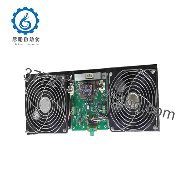
51303940-150
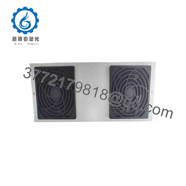
51303940-150
Installation & Configuration Guide
Stage 1: Pre-Installation Preparation — Approx. 10 Minutes
⚠️ Safety First
- Notify operations and obtain approval for the cabinet shutdown.
- Place the process in its defined safe state.
- Apply the site’s lockout/tagout procedure.
- Isolate the 120 VAC fan supply.
- Wait at least 5 minutes for stored energy to dissipate, or follow the cabinet-specific maintenance procedure.
- Verify absence of hazardous voltage with a properly rated multimeter.
Tools Required
- ESD wrist strap
- Digital multimeter
- Appropriate screwdriver
- Wire labels
- Smartphone/camera
- Replacement mounting hardware if required
Data Backup
- Photograph the complete 51303940-150 assembly.
- Photograph the fan wiring and alarm-contact wiring.
- Record the terminal numbers.
- Photograph airflow direction and fan orientation.
- Record the cabinet position.
- Document the alarm destination if it is wired into a DCS digital input or cabinet alarm circuit.
⚠️ Verify the voltage before ordering. Honeywell’s documentation identifies 51303940-150 as the 120 VAC MC-FAN611 assembly and 51303940-250 as the 240 VAC version.
Stage 2: Removing the Old Module — Approx. 5 Minutes
- Remove the cabinet access panel as required.
- Confirm the fan circuit is de-energized.
- Measure the supply rather than relying only on the cabinet breaker indication.
- Label the fan power wires.
- Label the alarm-contact wires separately.
- Disconnect the wiring without pulling on the conductors.
- Remove the fan assembly’s retaining hardware.
- Withdraw the assembly carefully.
- Inspect the cabinet opening and mounting surface.
- Check the wiring for heat discoloration or damaged insulation.
⚠️ Keep the old fan assembly until the replacement has passed the alarm and airflow tests.
Stage 3: Installing the New Module — Approx. 5–10 Minutes
- Wear a grounded ESD wrist strap when handling adjacent electronic hardware.
- Verify the replacement label reads 51303940-150.
- Confirm the voltage marking corresponds to the cabinet supply.
- Compare fan orientation with the original assembly.
- Confirm airflow direction.
- Install the assembly in the original mounting position.
- Tighten mounting hardware evenly.
- Reconnect the fan supply wiring.
- Reconnect the alarm contacts using the original terminal assignment.
- Ensure wiring cannot contact the fan blades.
Self-Checklist
- 51303940-150 verified
- 120 VAC supply verified
- Fan orientation matched
- Airflow direction matched
- Power wiring secured
- Alarm wiring secured
- Mounting hardware tightened
- No cable interference with fan blades
Stage 4: Power-On & Testing — Approx. 10 Minutes
Pre-Power Check
- Inspect the fan blades and housing for foreign objects.
- Verify the supply wiring.
- Check protective-earth continuity where applicable.
- Confirm alarm wiring against the original installation.
- Ensure the cabinet door or panel will not interfere with airflow.
Power-On Steps
- Energize the fan circuit.
- Confirm both fans start.
- Listen for abnormal bearing noise or vibration.
- Verify airflow direction.
- Confirm the cabinet alarm circuit remains in its normal state.
- Simulate an appropriate fan-fault condition if the maintenance procedure permits it.
- Verify that the alarm reaches the intended DCS or cabinet indication.
- Allow the assembly to run continuously while checking for abnormal temperature or vibration.
- Close the cabinet and confirm unrestricted airflow.
⚠️ Do not bypass the alarm contact simply because the fans are running. The alarm circuit is part of the cabinet’s thermal-protection strategy.
Technical Pitfalls
❗ 120 VAC vs. 240 VAC: This is the first replacement check. 51303940-150 is the 120 VAC version; 51303940-250 is the 240 VAC version.
❗ Alarm wiring: A fan can spin normally while its alarm circuit is incorrectly wired. Test the alarm separately rather than treating fan rotation as a complete acceptance test.
❗ Airflow direction: Installing the assembly backward can produce airflow even though the cabinet cooling path is wrong. Photograph the original direction before removal.
❗ Fan bearing condition: A replacement should be checked for abnormal noise, vibration, and startup behavior. A fan that starts slowly can indicate mechanical or electrical problems.
❗ Legacy stock condition: Radwell currently identifies 51303940-150 as discontinued by the manufacturer and lists different inventory conditions, including never-used original packaging and refurbished units.
Frequently Asked Questions (FAQ)
Q1. What is Honeywell 51303940-150?
The 51303940-150 is a Honeywell cabinet fan assembly with alarm. Honeywell’s model documentation identifies it as MC-FAN611, rated for 120 VAC. It belongs to the cabinet fan assemblies used with Honeywell process-control hardware.
Q2. Is 51303940-150 the same as 51303940-250?
No. They are different voltage versions. Honeywell’s model listing identifies 51303940-150 as 120 VAC and 51303940-250 as 240 VAC. Do not substitute one for the other without verifying the cabinet supply and wiring.
Q3. Is 51303940-150 obsolete?
Available industrial inventory information indicates that the part is discontinued by the manufacturer. Radwell specifically marks 51303940-150 as discontinued while still listing unused and refurbished inventory. This means procurement condition matters: “new” stock may represent remaining inventory rather than current production.
Q4. Is 51303940-150 a dual-fan assembly?
Yes. Supplier records identify the unit as a dual-fan cabinet assembly. Radwell lists it as a dual-fan, 120 VAC unit with an alarm function.
Q5. Can I replace the fan while the Honeywell DCS is running?
Do not assume that the fan assembly itself is hot-swappable. The correct procedure depends on how the cabinet fan power and alarm circuits are wired. If removing the assembly exposes hazardous 120 VAC conductors, isolate the circuit under the site’s lockout/tagout procedure.
Q6. Does the alarm connect directly to the Honeywell controller?
Not necessarily. The alarm contact can be wired into the cabinet’s alarm or DCS monitoring circuit, but the actual termination depends on the cabinet design. Photograph and document the existing alarm wiring before disconnecting it.
Q7. What condition should I specify when purchasing 51303940-150?
For a critical DCS cabinet, specify the condition explicitly: Factory Sealed, New Original/New Surplus, or Refurbished and Tested. Do not accept “available” as a condition description. Current market listings show multiple conditions for this discontinued part.
If replacing a failed unit in an operating Honeywell cabinet, provide the supplier with the 51303940-150 part number and photographs of the existing assembly, especially the voltage label, connector/wiring arrangement, and mounting configuration.



