
 WhatsApp: +86 16626708626
 Email:
  Phone: +86 16626708626
Description
3. Key Technical Specifications
| Parameter | Value |
|---|---|
| Part Number | 51304362-150 |
| Model / Catalog | MC-PLAM02 (also referenced as MU-PLAM02 family) |
| Input Channels | 32 galvanically isolated |
| Input Types | Thermocouple (J, K, E, T, B, S, R, RP), RTD (10 Ω, 100 Ω, 120 Ω), linear millivolt |
| Input Scan Rate | 32 samples per second (each channel once per second) |
| A/D Resolution | 14 bits |
| Typical Resolution | TC: 10 µV/bit; 100/120 Ω RTD: 64 mΩ/bit; 10 Ω RTD: 8 mΩ/bit; mV: 20 µV/bit |
| Common Mode Voltage | 250 Vac peak or ±250 Vdc (dc to 60 Hz) |
| Dielectric Strength | 1500 Vac rms or ±1500 Vdc channel-to-channel |
| Crosstalk | 120 dB (dc to 60 Hz) |
| Input Impedance | 2 MΩ min @ 100 mV |
| Max Continuous Input (no damage) | –1 V to +10 V |
| Line Frequency Sync | Configurable 50 or 60 Hz |
| Hardware Accuracy | ±40 µV or ±160 mΩ (at 23.5 °C ±2 °C) |
| Software Accuracy | ±0.1 °C typical, ±0.5 °C max (at 23.5 °C ±2 °C) |
| Redundancy Support | Not supported |
| Compliance | CE-compliant, conformal coated |
| System Compatibility | Honeywell TDC 3000 UCN, Process Manager (PM), Advanced Process Manager (APM), High Performance Process Manager (HPM); works with matching FTAs (e.g., MU/MC-TAMTxx, MU/MC-TAMRxx series) |
| Typical Dimensions / Weight | Approx. 2.8 × 37.8 × 27.8 cm; ~0.6 kg (verify exact on unit) |
4. Product Introduction
The Honeywell 51304362-150 (MC-PLAM02) is a Low Level Analog Input Multiplexer Processor (LLMux IOP) for TDC 3000 Universal Control Network systems. It conditions and multiplexes up to 32 low-level signals—thermocouples, RTDs, and millivolt inputs—from two 16-channel Field Termination Assemblies into the Process Manager family of controllers.
Field technicians select this module when they need dense, isolated low-level acquisition without redundancy. The conformal coating and CE marking make it suitable for many industrial environments where moisture or contamination is a concern. It remains a direct form-fit-function replacement for earlier non-coated or non-CE versions in the same family when the FTA wiring and configuration match.
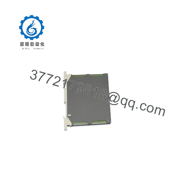
51304362-150
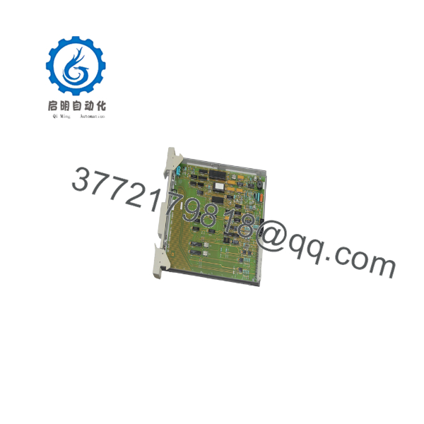
51304362-150
5. Installation & Configuration Guide
Stage 1: Pre-Installation Preparation (10–15 min) ⚠️ Safety First: Notify operations of planned downtime. Verify the process is in a safe state. Lock out / tag out all power sources to the cabinet and I/O rack. Wait at least 5 minutes for capacitors to discharge. Tools Required: Grounded ESD wrist strap, PH1 or appropriate screwdriver, digital multimeter (Fluke 115 or equivalent), wire labels, smartphone for photos. Data Backup: Export current configuration and logic from the engineering station. Photograph every DIP switch, jumper, and terminal wiring layout on the existing module and its FTAs. Note the exact firmware or personality of the host controller.
Stage 2: Removing the Old Module (5–10 min)
- Remove any front cover or bezel.
- Label and carefully disconnect all cables and FTA connections—do not force terminals.
- Release the rack or card-edge locking tabs and pull the module straight out to avoid bending backplane pins.
- Inspect the backplane connectors for bent pins, corrosion, or dust; clean if needed. ⚠️ Keep the old module available for reference until the new unit is fully operational and stable.
Stage 3: Installing the New Module (10–15 min)
- Put on the grounded ESD strap. Confirm the part number on the new module is exactly 51304362-150 (or the required revision).
- Configuration Clone (Critical): Set every DIP switch and jumper to match the photographs of the removed module. Pay special attention to any address, mode, or termination settings.
- Align the module with the backplane guides and insert firmly until the locking tabs click.
- Reconnect all wiring and FTA cables using the correct torque. Self-Checklist: [ ] Switches match photos [ ] Wiring secure and labeled [ ] Tabs locked [ ] No bent pins visible.
Stage 4: Power-On & Testing (10–20 min) Pre-Power Check: Use a multimeter to verify no shorts on the 24 V rail or power distribution.
- Apply power to the rack only (leave field devices offline if possible).
- Observe module LEDs—healthy status is typically steady green; solid red or flashing indicates a fault.
- Connect the engineering tool, confirm the IOP is recognized, and verify input status.
- Download or restore configuration if required.
- Perform a dry-run test: inject known low-level signals or short selected channels and confirm correct readings in the host controller. ⚠️ Troubleshooting Note: Solid red ERR often points to configuration mismatch or FTA incompatibility. No communication usually means address or backplane seating issues. Re-check switch settings and reseat the module before replacing power supplies.
6. Frequently Asked Questions (FAQ)
Q: Can I hot-swap the 51304362-150 under power? A: No. Power must be removed from the rack. Hot insertion risks backplane damage and can corrupt the IOP personality. Always lock out power first.
Q: Is this model obsolete, and is stock genuinely new? A: The TDC 3000 platform is mature and many components are limited-availability. Units we supply are new original or new surplus with full traceability. We perform inbound visual and functional checks; test reports are available on request. Confirm current stock before ordering.
Q: What is the direct replacement if 51304362-150 is unavailable? A: The non-coated or non-CE sibling (51304362-100 / MU-PLAM02) can often substitute if the environment and CE requirements allow. Always verify FTA compatibility and coating needs with the site drawings. Later Experion Series C or other families are not drop-in replacements.
Q: Will I lose my programming or configuration when I pull the old IOP? A: The control logic and point database reside in the Process Manager / APM / HPM, not on the IOP itself. You will not lose the application. However, any local IOP configuration (switches, personality) must be mirrored exactly on the new card.
Q: Why is the price lower than current OEM list? A: These are new surplus or carefully inspected stock from authorized channels and excess inventory. They carry our own warranty (typically one year) rather than a full factory new warranty. Functionality is verified under load before shipment.
Q: Does this module support redundancy? A: No. Redundancy is not supported on the LLMux IOP family. Plan accordingly for critical loops.
Q: What FTAs work with the 51304362-150? A: Compatible 16-channel FTAs include the MU/MC-TAMT and MU/MC-TAMR series (local or remote CJR versions). Confirm the exact FTA part numbers against the original installation drawings; CE and non-CE versions are not always interchangeable.



