
 WhatsApp: +86 16626708626
 Email:
  Phone: +86 16626708626
Description
Key Technical Specifications
| Parameter | Specification |
| Part Number | 51304511-200 |
| Alternate Part Number | 51304511-100 / MC-TTRX02 |
| Network Protocol | Honeywell Local Control Network (LCN) / Universal Control Network (UCN) |
| Fiber Type | Multimode Fiber (62.5/125 µm or 50/125 µm) |
| Optical Wavelength | 850 nm nominal |
| Connector Type | ST Duplex Connectors |
| Backplane Power Draw | 5 V DC, 0.8 A max |
| Operating Temperature | 0^\circC to +60^\circC |
| Transmission Distance | Up to 2.0 km (1.2 miles) via standard multimode fiber |
| Form Factor | Single-slot DCS Card Cage Module |
| Mounting | Standard Honeywell High-Performance Process Manager (HPM) Card Rack |
Product Introduction & Supply Chain Strategy
The Honeywell 51304511-200 is a critical Local Control Network (LCN) fiber optic transceiver module used across Honeywell TDC 3000 systems. It translates electrical backplane signals into optical pulses, enabling high-speed, noise-immune communication between control nodes, operator stations, and remote I/O racks separated by long physical distances or severe electrical noise.
Securing this module as New Surplus ensures uncompromised optical power output and signal integrity without risking internal laser diode attenuation or component drift typical of aged hardware. In high-density industrial control environments, an optical transceiver degradation can cause intermittent node drops or signal packet losses. Sourcing factory-fresh New Surplus units minimizes Total Cost of Ownership (TCO) by maintaining full system reliability, avoiding long OEM production lead times, and preventing emergency plant shutdowns.
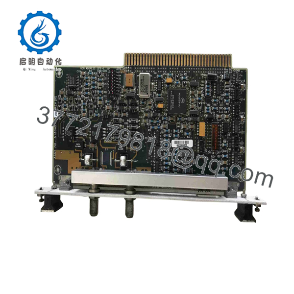
51304511-200
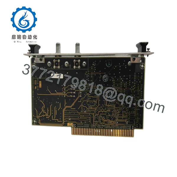
51304511-200
Installation & Configuration Guide
Stage 1: Pre-Installation (Prep & Safety)
- Safety & LOTO: Verify system redundancy before powering down the specific slot or card cage segment.
- ESD Protection: Attach a grounded ESD wrist strap before removing the module from its protective anti-static bag.
- Optics Inspection: Inspect optical ports and fiber cable tips for contamination. Keep protective dust caps installed on unused fiber ports.
Stage 2: Removal
- Label all fiber optic patch cables (TX and RX positions) connected to the existing board.
- Disconnect the fiber ST connectors gently by pushing in and twisting counter-clockwise. Immediately cap the fiber ends.
- Loosen the top and bottom card cage retaining screws and pull the old module straight out of the rack guide using the faceplate tabs.
Stage 3: Installation (Clone & Seat)
- Check the 51304511-200 circuit board for any DIP switches or jumper settings and align them with the old board’s configuration.
- Align the module with the card guide rails and slide it firmly into the slot until the backplane connectors seat completely.
- Tighten the top and bottom retaining thumbscrews to ensure solid chassis grounding.
- Remove dust caps and reconnect the fiber optic cables to the designated TX and RX ports.
Stage 4: Power-On & Testing
- Re-energize the card rack power supply if it was isolated.
- Observe the front panel diagnostic LEDs; confirm that the power LED is solid green and the communication link indicator stabilizes.
- Verify at the operator console that the network node communicates without packet errors or optical link alarms.
Firmware/Software Versions & Upgrade Notes
- Firmware/Hardware Dependency: The 51304511-200 operates as a hardware-level optical media converter and does not require standalone software flash loading.
- Compatibility: Fully backward and forward compatible with legacy Honeywell TDC 3000 LCN architectures, High-Performance Process Managers (HPM), and Universal Control Network (UCN) bridge nodes.
- Hardware Revision Advisory: When replacing older revision cards (e.g., 51304511-100), ensure optical launch power levels match across the link to avoid receiver saturation or signal degradation on longer fiber runs.
Frequently Asked Questions (FAQ)
Q: Is this Honeywell 51304511-200 module new surplus or pulled from a working system?
A: This product is guaranteed New Surplus / Original New. It has never been installed in an active process plant, repaired, or refurbished. It comes from clean, verified inventory stock in original anti-static packaging.
Q: Why choose New Surplus over a lower-cost refurbished fiber board?
A: Fiber transceiver modules rely on solid-state laser diodes and optical receivers that degrade over operating hours. Refurbished boards carry used optical transmitters that may suffer reduced launch power, leading to intermittent node drops under heavy network traffic. New Surplus offers 100% optical output lifespan at a fraction of standard OEM costs.
Q: What fiber cable type is supported by the 51304511-200?
A: This module is designed for multimode optical fiber (typically 62.5/125 µm) operating at a 850 nm wavelength with standard ST connectors.
Q: Can I hot-swap this module while the system is powered on?
A: Hot-swapping depends on your specific cabinet and rack design. While many HPM card racks permit hot insertion, standard operating procedure recommends taking the specific node off-line or setting the redundant link active before extracting network-critical communications cards to prevent system upsets.
Q: What warranty coverage comes with this module?
A: Every New Surplus 51304511-200 transceiver module is backed by a full 1-year functional replacement warranty from the date of dispatch.



