
 WhatsApp: +86 16626708626
 Email:
  Phone: +86 16626708626
Description
Key Technical Specifications
- Manufacturer: Honeywell
- Part Number: 51402614-100
- Product Type: K2LCN motherboard / main PCB / processor-card carrier board
- System Family: Honeywell TDC 3000 / TotalPlant Solution legacy Local Control Network hardware
- Primary Application: K2LCN node chassis and processor-board assembly
- Known Processor Assembly Reference: 51402615-400
- Known K2LCN Variant Reference: K2LCN-4
- Known Processor Assembly Reference: 51402615-800
- Known K2LCN Variant Reference: K2LCN-8
- Known Board Revision Example: Rev. D shown in a -8 listing
- Functional Role: Provides the physical motherboard interface for the processor-card assembly and related node hardware
- Network Context: Honeywell LCN architecture; verify actual installed communications hardware and network interface separately
- Connector and Backplane Requirement: Match board-edge connections, chassis guides, daughterboard locations, and all cable interfaces
- Firmware Dependency: Processor-card firmware and node configuration are application-specific; verify before replacement
- Interchangeability: Do not assume -4 and -8 assemblies are interchangeable based on shared motherboard part number
- Replacement Requirement: Match 51402614-100, board revision, installed processor assembly, node type, chassis, and companion-board configuration
Market listings show 51402614-100 paired with both 51402615-400 as a -4 motherboard assembly and 51402615-800 as a -8 processor-card assembly. Those records support identifying 51402614-100 as motherboard hardware, not as a generic Ethernet, analog-output, or C300 I/O module.
Product Introduction
The Honeywell 51402614-100 is a motherboard used in legacy Honeywell TDC 3000 and TPS Local Control Network hardware. It provides the primary board-level platform for processor-card assemblies, related node electronics, and chassis interconnections within the LCN architecture.
This board is purchased as an exact legacy replacement when a node has motherboard, connector, or board-level hardware damage. Compatibility depends on the processor-card assembly, motherboard revision, chassis type, companion boards, and installed node configuration. A physical fit does not prove that a replacement will boot or communicate correctly on the LCN.
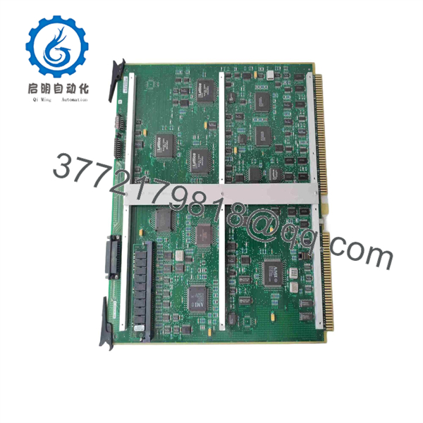
51402614-100
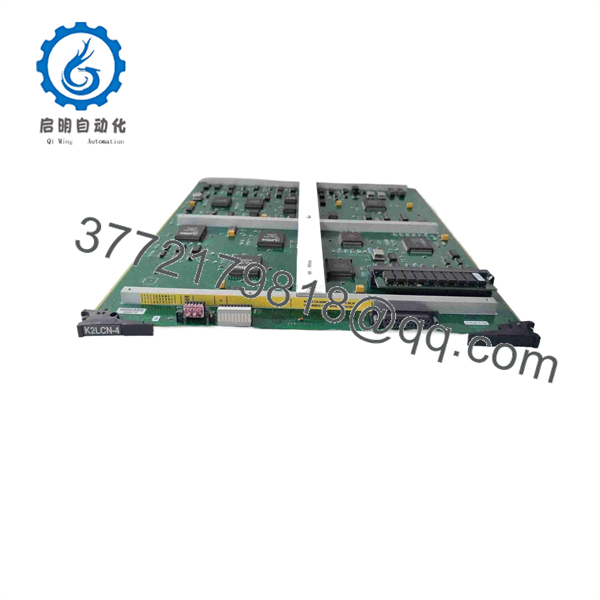
51402614-100
Troubleshooting Quick Reference
| Symptom | Possible Cause | Relevance to This Part | Quick Check Method | Recommendation |
|---|---|---|---|---|
| node does not power up | Chassis power failure, blown fuse, failed power system, poor board seating, motherboard fault | ⚠️ Medium | Check chassis supply rails at approved test points, power-system indicators, fuses, and board seating before removal | Repair the power path before replacing the motherboard |
| Node powers up but does not join the LCN | Network-interface issue, coax or fiber cable fault, incorrect node configuration, processor-card fault, motherboard interface fault | ⚠️ Medium | Review LCN diagnostics, inspect communications cabling and related interface boards, then compare node configuration with the approved system record | Verify network and processor hardware before replacing 51402614-100 |
| Random node resets or intermittent communication loss | Weak power rails, overheating, connector oxidation, backplane contact issue, aging motherboard components | ✅ High | Trend reset events, inspect cabinet temperature and airflow, reseat board assemblies during an approved outage, and inspect contacts under magnification | Correct power, cooling, and connector issues before replacing the board |
| Fault begins immediately after a replacement | Wrong motherboard revision, incompatible processor assembly, missing companion board, bent connector, incorrect chassis location | ✅ High | Compare old and replacement units side by side: part number, revision, processor-card number, connector placement, jumpers, and component population | Stop commissioning until all differences are resolved |
| One node is offline while others remain healthy | Local processor-board problem, local power issue, motherboard fault, cable or node-interface fault | ⚠️ Medium | Compare node LEDs and fault logs against a healthy node; verify local chassis power and network cable seating | Isolate the local node fault before ordering hardware |
| Multiple LCN nodes fail together | Shared LCN trunk fault, shared power issue, network termination fault, central network component issue | ❌ Low | Compare alarms across nodes and inspect common infrastructure, common power sources, and network equipment | Do not replace one motherboard until shared infrastructure is cleared |
| Processor board does not seat correctly | Bent board guides, damaged connector, incorrect processor-card version, warped board, foreign object in slot | ✅ High | Inspect chassis card guides, connector pins, extractor hardware, and board edges with power isolated | Do not force the processor board into the motherboard |
| Visible corrosion, burnt components, or damaged traces | Moisture, contaminated cabinet, overvoltage, failed power supply, previous repair damage | ✅ High | Inspect both board sides under good lighting for corrosion, residue, scorched traces, broken connectors, and rework marks | Remove from service and investigate root cause before fitting a replacement |
Field warning: A motherboard is rarely the first cause of an LCN communication fault. Check local chassis power, the processor assembly, cabling, node configuration, and common network infrastructure before replacing board hardware. If several nodes fault together, the issue is almost certainly outside one motherboard.
❗ Do not buy it as an Ethernet board: Several generic online pages call 51402614-100 an Ethernet board or a C300 analog-output module. Those claims conflict with listings that identify it as motherboard hardware paired with -4 and -8 processor assemblies. Do not use generic Ethernet or analog-I/O specifications to wire, configure, or test this board.
❗ Processor-card match is mandatory: Record the installed processor-card label before removing anything. Listings show 51402615-400 associated with and 51402615-800 associated with . That does not establish every valid combination, but it proves the motherboard must be evaluated with its installed processor assembly.
❗ Firmware mismatch creates long outages: Do not assume a processor card will boot correctly simply because it seats in the replacement motherboard. Record firmware stickers, EPROM labels, programmable-device labels, node configuration, and any service tags. I have seen a replacement board install cleanly, then leave a node offline because the technician did not preserve the original hardware pairing and configuration record.
❗ Photograph every cable and board position: Take clear photos of board order, chassis slot location, board guides, cable routing, jumpers, and connectors before removal. It is the most common rookie mistake, but it happens constantly. Take a picture before you touch anything. Seriously.
❗ Never force card-edge connectors: If the processor assembly does not seat with normal, even pressure, stop. Check alignment, card guides, connector condition, missing standoffs, and the exact board assembly. Forcing a legacy connector can damage the motherboard and an irreplaceable processor card.
❗ ESD protection is not optional: Use a grounded wrist strap, ESD mat, and antistatic packaging. Legacy motherboard logic can fail from static damage without showing visible burn marks. Handle only by board edges and mounting hardware.
Keep these checks in mind and you will save yourself 90% of typical rework time. If the cause remains uncertain, provide technical support with photos of both sides of the installed motherboard, processor-card and firmware labels, chassis type, node diagnostics, power-rail measurements, and the relevant LCN schematic.
Frequently Asked Questions
What is Honeywell 51402614-100?
Honeywell 51402614-100 is motherboard hardware used in legacy Honeywell TDC 3000 / TPS Local Control Network applications. Resale records show it paired with processor-card assemblies, including 51402615-400 for -4 and 51402615-800 for -8.
Is 51402614-100 an Ethernet module?
Do not treat it as a generic Ethernet module. Some reseller pages label it that way, but the more specific assembly listings identify it as a motherboard used with -4 processor hardware. Verify the physical board label and Honeywell equipment documentation before assigning any Ethernet or TCP/IP function to the part.
Is 51402614-100 an analog-output module?
No reliable source supports using it as an analog-output module. One generic listing claims it is an eight-channel C300 analog-output product, but that description conflicts with the processor and motherboard assembly records. Do not connect 4–20 mA or field I/O wiring to a 51402614-100 based on that claim.
Can I use the same motherboard ?
Only if Honeywell documentation for your exact chassis and node configuration confirms it. The same 51402614-100 motherboard number appears in listings with assemblies, but that alone does not prove universal interchangeability. Match board revision, processor card, firmware, companion boards, chassis type, and network configuration.
Can I hot-swap the 51402614-100 motherboard?
No. Do not hot-swap a motherboard or remove its processor assembly with the node energized unless Honeywell’s exact service procedure explicitly allows it. This hardware supports network-node operation. Removing it live can take the node offline, damage the card-edge connector, corrupt communications, or create process alarms.
Will replacing the motherboard erase the node configuration?
It can. Configuration and firmware may reside on the processor card, EPROMs, nonvolatile memory, or external node software. Before removal, back up available engineering data, document node addressing and network configuration, photograph all labels and jumper settings, and retain the original processor card with the original board until the replacement is verified.
Is Honeywell 51402614-100 obsolete?
Yes. It should be treated as a legacy Honeywell TDC 3000 / TPS spare. Current market visibility is mainly through surplus and used inventory, including open-box and used assemblies. Procurement should verify actual stock, board revision, processor-card compatibility, condition, and test evidence before issuing a purchase order.
Why can a New Surplus motherboard cost less than an OEM replacement?
New Surplus hardware often comes from unused maintenance inventory, cancelled upgrades, warehouse liquidation, or legacy system decommissioning. It may be unused but not factory sealed. For a board of this age, require actual high-resolution photographs, visible revision markings, storage-condition information, connector inspection, test evidence, warranty terms, and a clear return process.
What testing should a supplier perform before shipment?
For a Honeywell 51402614-100 motherboard, request testing specific to the offered unit:
- Verify the exact 51402614-100 part number, revision, serial data, and all visible assembly labels
- Photograph both sides, including board-edge connectors, processor-card slots, jumpers, standoffs, cable headers, and any companion-board interfaces
- Inspect for corrosion, bent contacts, cracked solder joints, rework marks, damaged traces, overheated components, and missing hardware
- Confirm mechanical fit with the matching processor assembly and compatible chassis hardware
- Test power-up only in a verified chassis with correct supply rails and correctly matched processor hardware
- Verify node boot behavior and stable LCN communication through the applicable network-interface arrangement
- Run long enough to detect intermittent resets, connector issues, abnormal current draw, or thermal instability
- Record the test configuration, processor-card part number, firmware labels, run duration, node diagnostics, and results
- Package in ESD-safe material with foam support and heavy-duty boxing, then provide QC sign-off and warranty terms
Test photos and videos should be available upon request. A supplier should identify whether the offered board is New Original / New Surplus, Refurbished (tested), or Used Removed From Working Equipment.



