
 WhatsApp: +86 16626708626
 Email:
  Phone: +86 16626708626
Description
Key Technical Specifications
| Parameter | Value |
|---|---|
| Manufacturer | Honeywell Process Solutions |
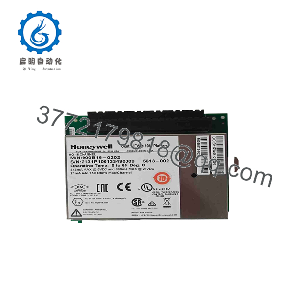
| Model Number | 900B16-0202 |
| Product Series | ControlEdge HC900 |
| Product Type | Analog Output Module / Analog Output Card |
| Output Channel Count | 16 channels |
| Output Signal | 0 to 20 mA analog current output |
| Maximum Output Capability | 21 mA into 750 Ω maximum load per channel |
| Output Use | Modulating control of final elements, such as valve positioners, I/P converters, SCR power controllers, VFD references, and remote analog setpoints |
| Operating Ambient Temperature | 0 to +60 °C |
| Controller Platform | Honeywell ControlEdge HC900 modular process controller |
| Rack Limitation | Two 900B16-0202 modules per HC900 rack, per available reseller specification; verify against the installed rack configuration |
| Configuration Method | Configured in HC900 engineering software and assigned to the installed controller/rack I/O database |
| Installation Requirement | Correct HC900 I/O rack or carrier position, compatible terminal assembly, correct channel mapping, and documented commissioning checks |
| Lifecycle Status | Current ControlEdge HC900 family hardware; stock condition, lead time, and regional availability vary by supplier |
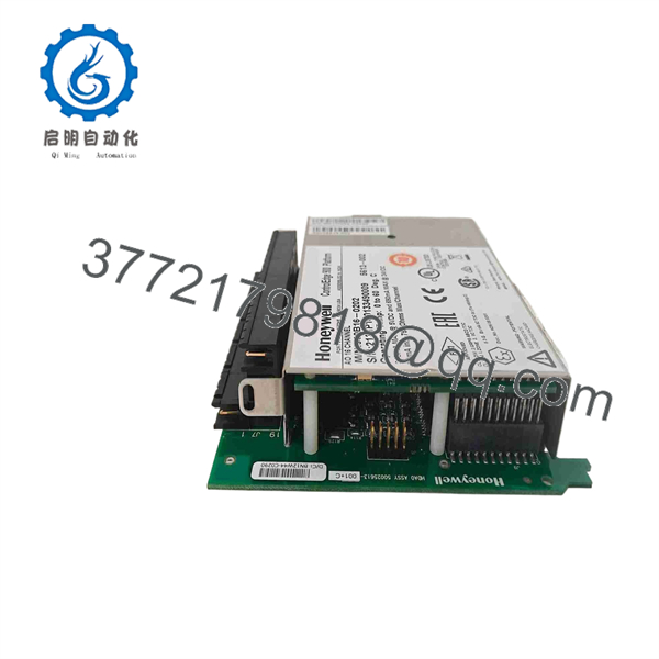
The Honeywell 900B16-0202 is a ControlEdge 16-channel analog output card specified for 0–20 mA outputs. Distributor information lists 21 mA into a 750 Ω maximum load per channel and a 0 to +60 °C operating range. Honeywell positions the as a modular process controller for thermal and process applications such as boilers, furnaces, kilns, dryers, and other continuous or batch control systems.
Product Introduction
The Honeywell 900B16-0202 is a 16-channel, 0–20 mA analog output module for the ControlEdge process-control platform. It converts control strategies into current outputs for field devices such as control valve positioners, I/P transducers, variable-frequency-drive speed references, power controllers, and remote setpoint inputs.
This module fits applications that need a high channel density of current outputs within a single I/O system. Verify the required output range, field-device input impedance, configured channel scaling, terminal assembly, and rack loading before ordering. Do not substitute it for voltage-output or analog-input hardware.
900B16-0202
900B16-0202
Troubleshooting Quick Reference
| Symptom | Possible Cause | Relevance to this Part | Quick Check Method | Recommendation |
|---|---|---|---|---|
| All 16 analog outputs read 0 mA | Module not powered, rack communication issue, controller in stop/fault state, incorrect I/O database configuration | ✅ High | Check the controller and rack status indicators. Confirm the module is fully seated and review the engineering configuration for module recognition and rack assignment. | Verify controller health, rack power, and configuration before replacing the output module. |
| One channel remains at 0 mA | Incorrect control strategy output, bad channel configuration, open field wiring, failed output channel, field device fault | ✅ Medium | Force or manually command the channel using the approved commissioning procedure. Measure current in series with the loop at the terminal assembly using a calibrated milliamp meter. | Check configuration, field wiring, and device input first. Replace the module only if the configured output fails at the module terminal. |
| Output is fixed near 20 or 21 mA | Controller strategy at high demand, manual output hold, incorrect scaling, short/open loop response, failed channel | ✅ Medium | Review the operator display and engineering configuration for manual mode, output limits, alarms, and control-block values. Measure loop current and compare it with the commanded percentage. | Correct configuration or process demand first. Investigate the field loop before replacing the module. |
| Valve or VFD does not respond, but output current is correct | Failed positioner, I/P converter, VFD analog-input setup, broken actuator linkage, field device power problem | ❌ Low | Measure the actual current at the field device input. For a valve loop, check instrument-air supply, positioner diagnostics, actuator movement, and linkage. | The module is likely healthy if correct current reaches the field device. Repair the field device or actuator system. |
| Output signal is unstable or noisy | Improper shield grounding, analog cable routed near VFD/motor cables, loose terminals, unstable control tuning, poor field-device input | ❌ Low to medium | Trend the output value and compare it with a series loop-current measurement. Inspect shield termination and route separation from high-energy cables. | Correct wiring, grounding, and tuning issues before replacing the output card. |
| Module reports I/O fault or is not recognized | Incorrect module placement, bent connector pin, damaged rack/backplane, incompatible configuration, failed module | ✅ High | Power down under approved procedure, inspect the module connector and rack contacts, then compare the configured module type and slot assignment with the physical installation. | Reseat the module and correct configuration. Replace it if it remains unrecognized in a verified-good slot. |
| New module causes outputs to move incorrectly | Channel mapping error, incorrect output scaling, swapped terminal wiring, wrong control strategy assignment | ✅ High | Before energizing final elements, place loops in manual and compare each configured channel with the physical terminal and field tag. Perform a documented 0%, 50%, and 100% loop check. | Correct channel mapping and scaling. Do not release the system to automatic control until each output is proven. |
| Several channels drop out when loads are connected | Aggregate rack-power issue, field-loop wiring fault, load impedance too high, shared common issue, module failure | ✅ Medium | Disconnect field loads one at a time under approved procedures. Verify each loop load does not exceed 750 Ω and monitor the rack power supply under load. | Correct external load and wiring issues first. Replace the module only if failures remain with known-good loads. |
| Burned terminal, heat discoloration, or damaged electronics | Wiring short, external overvoltage, incorrect common connection, lightning/surge event, failed field device | ✅ High | Isolate power, inspect terminal assemblies and wiring, then test each connected loop for shorts or unintended voltage before fitting a replacement. | Replace the damaged module and fix the field fault before energizing the replacement. |
❗ Do not confuse 0–20 mA with 4–20 mA: The hardware is specified as 0–20 mA. A 4–20 mA control loop may be achieved through configuration, but verify the documentation and control strategy before commissioning. A wrong low-end configuration can drive a valve closed, open, or into fault at startup.
❗ Check loop resistance, not only continuity: Each channel is specified for up to 21 mA into 750 Ω maximum load. A loop can pass a continuity test but still exceed the output capability because of long cable runs, isolators, barriers, positioner input resistance, and series devices.
❗ Prove every channel before returning to automatic: I have seen a 16-channel output card replaced correctly but wired one terminal block offset. The result was a valve response on the wrong loop. Place outputs in manual, isolate process impact, and document a 0%, 50%, and 100% loop test.
❗ Photograph terminal blocks before removal: Take clear photos of every terminal, shield, common, and tag. output modules are straightforward until a shared common or field cable lands on the wrong point.
❗ Use ESD controls: Wear a grounded wrist strap and keep the module in ESD-safe packaging until installation. A static event can damage an analog channel without creating visible board damage.
Keep these checks in mind and you will save yourself 90% of typical rework time. If the diagnosis remains uncertain, contact technical support with module and terminal-block photos, diagnostics, configured channel assignments, commanded output values, and measured loop currents.
Frequently Asked Questions
What is the Honeywell 900B16-0202?
The Honeywell 900B16-0202 is a ControlEdge analog output module with 16 current-output channels. It is specified for 0–20 mA output service, with a stated maximum capability of 21 mA into 750 Ω per channel. It is used to send controller commands to analog field devices in process-control systems.
Can I use the 900B16-0202 for a 4–20 mA control valve?
Potentially, but confirm the output configuration in the engineering database and verify the control valve positioner or I/P converter expects a 4–20 mA input. The module is publicly specified as 0–20 mA hardware. Configure, test, and document the output scaling before connecting it to a live final control element. Do not assume every channel is factory-configured for 4–20 mA.
How many channels does this module provide?
It provides 16 analog output channels. This high density makes it suitable for systems with multiple modulating valves, damper actuators, VFD references, power-controller commands, or remote analog setpoints.
What is the maximum load resistance for each output?
The published specification is 21 mA into a maximum 750 Ω load per channel. Include all series loop resistance in that calculation: field wiring, intrinsic-safety barriers, isolators, terminal hardware, signal conditioners, and the field device input. If the load exceeds the rating, the output may not achieve its commanded current.
Can I hot-swap the 900B16-0202?
Do not assume hot swapping is safe for your process. The platform and the installed I/O arrangement may support maintenance procedures that permit module replacement, but removing an analog output card can drive outputs to zero, hold their last state, or trigger I/O faults depending on configuration and system design. Coordinate with operations, put affected loops in a safe manual state, bypass or isolate final elements where approved, and follow the applicable Honeywell procedure.
Will I lose my program when I replace the module?
Your main control strategy and engineering configuration normally reside in the controller project rather than the analog output card. However, replacing the hardware can cause I/O recognition, channel configuration, scaling, or mapping issues. Back up the controller project, record the slot assignment, photograph terminal wiring, export or document the I/O database, and perform loop checks after replacement.
Why does the valve not move even though the module output is correct?
If you measure the correct current at the field-device terminals, the 900B16-0202 is likely doing its job. Check the valve positioner, I/P converter, instrument-air supply, actuator diaphragm, linkage, valve stiction, VFD analog-input selection, and field-device configuration. Do not replace a healthy output module because the final element failed to respond.
Is the 900B16-0202 obsolete?
Honeywell continues to present ControlEdge as an active modular process-controller platform. Actual availability of the exact 900B16-0202 module can still vary by region, distribution channel, stock level, and lead time. Confirm the current delivery commitment and product condition before issuing a purchase order.
What condition and test documentation should I request?
For New Original or New Surplus inventory, request photos of the factory label, packaging, seal condition, date code, and terminal or connector area. For a refurbished unit, request documented inspection, rack power-up, module-recognition verification, per-channel current-output tests, load testing up to the specified resistance, ESD-safe packaging confirmation, and a dated test report. Test videos and photos should be available upon request.



