
 WhatsApp: +86 16626708626
 Email:
  Phone: +86 16626708626
Description
Key Technical Specifications
| Parameter | Value |
|---|---|
| Manufacturer | Honeywell |
| Model Number | CC-PAIH01 |
| Common Material Number | 51405038-175 |
| Product Type | High-Level Analog Input / HART Input Module |
| Product Family | Experion PKS Series C I/O |
| Controller Compatibility | Honeywell C300 Controller architecture |
| Input Channels | 16 analog input points |
| Primary Signal Type | High-level current input from field transmitters |
| Typical Current Input | 4–20 mA DC |
| HART Capability | HART communication and device-status access |
| HART Application | Primary variable, status, configuration, secondary and tertiary variables where configured |
| Voltage Input Capability | Channels 13–16 support voltage inputs when IOTA jumpers are modified |
| Standard Input Topology | Channels 1–12 normally configured as single-ended current inputs |
| Differential Input Capability | Channels 13–16 can be configured for differential operation within common-mode voltage limits |
| Field-Power Function | Individually protected, current-limited transmitter field power circuits |
| Open-Wire Detection | Supported for configured analog input loops |
| Input Load Resistor | 250 Ω resistor connected through IOTA jumper for current-input applications |
| IOTA Requirement | Compatible Series C analog-input IOTA; verify exact IOTA part number and redundancy arrangement |
| IOTA Size | Normally 6-inch IOTA, 152 mm, for nonredundant analog applications |
| Redundant IOTA Arrangement | Normally 12-inch IOTA, 304 mm, for redundant analog applications |
| Module Diagnostics | Module, channel, open-wire, and field-device diagnostic reporting |
| Power Source | Honeywell Series C I/O power system / backplane |
| Operating Temperature | Verify against the exact Honeywell datasheet and installed enclosure conditions |
| Installation Environment | Control cabinet or approved Class I, Division 2 installation when installed per Honeywell control drawings |
| Engineering Requirement | Compatible Experion release, Control Builder configuration, IOTA wiring, and HART device definitions |
Honeywell identifies the CC-PAIH01 as a 16-point high-level analog input/HART input module for Series C I/O. It accepts typical 4–20 mA transmitter signals, supports HART information for device status and configuration, and provides voltage-input options on channels 13–16 after IOTA jumper changes.
Product Introduction
The Honeywell CC-PAIH01, material number 51405038-175, is a 16-point Series C high-level analog input module with HART support for Experion PKS systems using the C300 controller. It reads 4–20 mA process signals from pressure, flow, level, temperature, and analytical transmitters while bringing HART device information into the control and asset-management environment.
The CC-PAIH01 is selected when the plant needs standard analog control values plus HART diagnostics and device parameters without adding separate multiplexers. Channels 13–16 can be adapted for voltage input or differential operation through compatible IOTA jumper changes. Verify the installed IOTA, field wiring, system release, and channel configuration before ordering.
Troubleshooting Quick Reference
| Symptom | Possible Cause | Relevance to this Part | Quick Check Method | Recommendation |
|---|---|---|---|---|
| All 16 channels show bad quality or no process values | Series C I/O power loss, failed IOTA/header connection, module fault, controller communication loss | ✅ High | Check cabinet power distribution and confirm the I/O module status in Experion. Inspect module seating, IOTA engagement, carrier connections, and associated controller diagnostics. | Verify power and I/O communication before replacing the CC-PAIH01. A total loss of all channels can indicate a module, IOTA, carrier, or cabinet power problem. |
| One channel reads 0 mA or underrange | Open field loop, failed transmitter, broken wire, incorrect terminal landing, channel failure | ❌ Usually external | Measure loop current with a calibrated meter at the IOTA terminals. Confirm 24 V DC field power, transmitter polarity, and continuity from transmitter to cabinet. | Check the field loop first. Replace the module only if a known-good loop fails on the same channel and operates correctly on another verified channel. |
| One channel reads 20 mA or overrange | Transmitter failure, wrong range setup, shorted loop, improper field wiring, incorrect signal configuration | ❌ Usually external | Measure actual loop current at the terminal. Compare the transmitter’s local indication and configured range against the Control Builder point configuration. | Correct transmitter calibration, wiring, or configuration. Do not replace the module until the actual current and configured engineering range agree. |
| Several adjacent channels read incorrectly | Common return issue, IOTA damage, incorrect shared wiring, field-power distribution fault | ✅ Medium | Inspect the analog IOTA for bent terminals, loose jumpers, damaged traces, and incorrect common wiring. Compare affected channels against the wiring diagram. | Isolate wiring before replacing the module. If the fault follows the physical IOTA location after a module substitution, investigate the IOTA and terminal assembly. |
| HART device shows analog PV but no digital diagnostics | HART device not configured, loop impedance issue, incorrect HART setup, excessive loop noise, unsupported device description | ❌ Usually external/configuration | Verify stable 4–20 mA operation first. Confirm HART device address, HART configuration, device description, and field-loop wiring. Review HART diagnostics in Experion/FDM. | Keep the analog module in service unless all known-good HART devices fail on the same channels. HART problems are commonly configuration or loop-quality issues. |
| HART communication drops intermittently | Noise, grounding issue, poor shield termination, unstable transmitter power, multidrop configuration error | ❌ Usually external | Trend HART communication errors and compare them with nearby VFD starts, relay switching, or power disturbances. Inspect shield termination and transmitter power stability. | Correct shielding and field wiring. Do not ground the cable shield at both ends unless the site grounding design specifically requires it. |
| Voltage input on channels 13–16 reads incorrectly | 250 Ω IOTA jumper not cut, incorrect differential wiring, common-mode voltage exceeded | ✅ High | Inspect the IOTA jumpers for the affected channel. Confirm whether the signal is intended as current, single-ended voltage, or differential voltage. Measure the signal directly at the terminals. | Set the IOTA jumper arrangement for the actual signal type. Do not assume channels 1–12 and 13–16 have identical wiring behavior. |
| Channel reads a fixed value despite changing transmitter output | Wrong Control Builder point assignment, incorrect channel mapping, forced value, frozen scan, damaged IOTA terminal | ❌ Usually configuration | Check the controller point assignment, channel number, engineering range, simulation/force status, and raw input value. Apply a known test current using a loop calibrator. | Remove unauthorized forces and correct point mapping. If a known test signal does not change the raw value on one channel, test the IOTA and then the module. |
| Field transmitter has no loop power | Field-power circuit issue, wiring short, transmitter fault, external fuse or cabinet supply problem | ✅ Medium | Measure field supply voltage at the transmitter and at the IOTA. Disconnect the field circuit and determine whether the supply recovers. | Locate shorts or failed transmitters first. The module provides protected current-limited field-power circuitry, so confirm the load condition before replacing hardware. |
| Replacement module does not operate after installation | Wrong module revision, incorrect IOTA, IOTA jumpers not copied, incompatible engineering database, ESD damage | ✅ High | Photograph old module and IOTA labels, terminal positions, jumper cuts, and wiring before removal. Confirm the installed part is CC-PAIH01, not a different Series C analog variant. | Match the original hardware and configuration exactly. Test with one known-good 4–20 mA loop before returning the old module as failed. |
The CC- rarely fails one channel at a time without evidence of external loop damage, wiring problems, terminal issues, or transmitter faults. Start with live loop-current measurements and raw controller diagnostics before replacing a 16-channel analog input module.
❗ Firmware and engineering warning: Document the installed Experion release, Control Builder project revision, module catalog entry, channel assignments, and HART device configuration before pulling the old unit. A physically correct module can still remain unrecognized if the engineering database does not match the installed hardware.
❗ IOTA jumper warning: On the CC-, channels 13–16 can use voltage inputs only when the appropriate IOTA jumpers are modified. Take clear photos before removing anything. It is the most common replacement mistake with this module family.
❗ Wiring warning: Do not wire from memory. Verify the exact IOTA terminal diagram and the configured signal type. A 4–20 mA loop wired as a voltage input, or a voltage source landed on a current-input channel with its 250 Ω resistor intact, produces misleading readings and can create a long troubleshooting shift.
❗ Power-budget warning: Confirm total Series C I/O and field-power loading before installation. Leave at least a 20% margin on the cabinet 24 V DC supply. A power supply that sags under transmitter load can make healthy analog modules look defective.
❗ ESD warning: Wear a grounded wrist strap and use an ESD-safe work surface. I have watched a technician handle a costly analog card during dry weather, install it, and find that it failed on power-up. Use the wrist strap.
Keep these checks in mind and you will save yourself most of the usual analog-loop rework time. If the problem remains unclear, send technical support photos of the module label, IOTA label, field terminals, jumper settings, controller diagnostics, and measured loop values.
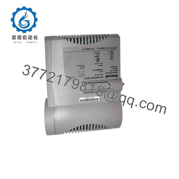
CC-PAIH01
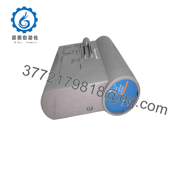
CC-PAIH01
Frequently Asked Questions
What does the Honeywell CC- do?
The Honeywell CC- is a Series C high-level analog input module for Honeywell Experion PKS systems using C300 controllers. It accepts analog field signals, typically 4–20 mA DC from process transmitters, and supports HART communication for smart device diagnostics, configuration, and additional variables. Honeywell specifies it as a 16-point high-level analog/HART input module.
How many inputs does the CC- have?
The CC- provides 16 analog input points. For standard process applications, these points receive high-level current signals from field transmitters. Honeywell documentation describes channels 13–16 as having additional voltage-input and differential-operation options when the applicable IOTA jumpers are modified.
Can I connect standard 4–20 mA transmitters without HART?
Yes. You can use ordinary non-HART 4–20 mA transmitters on the CC-. HART is an additional digital signal superimposed on the analog loop; it is not required for the analog process variable to work. For a basic pressure, level, flow, or temperature transmitter, configure the channel as the correct current-input type and set the engineering range in the control strategy.
Can I connect voltage signals to this module?
Yes, but do not assume every channel has identical voltage-input behavior. Honeywell documentation indicates that channels 13–16 can support voltage inputs after the user modifies the wire jumper on the compatible IOTA. The standard 250 Ω current-input resistor must be disconnected for that use case. Verify the exact IOTA drawing, signal range, common-mode limits, and field wiring before applying voltage.
What is the difference between the CC- and a low-level RTD/thermocouple input module?
The CC- handles high-level analog signals such as 4–20 mA transmitter loops and selected voltage inputs. It is not the correct module for direct RTD or thermocouple wiring. RTDs and thermocouples use low-level input modules that provide sensor excitation, cold-junction compensation where required, and specialized open-sensor diagnostics. Do not attempt to land a thermocouple directly on a CC-.
Can I hot-swap the CC-?
Do not treat it as a casual hot-swap. The Series C platform supports serviceability features, but removing an analog input module can interrupt process measurement, trigger bad-quality indications, cause alarms, and affect control loops. Put affected loops in an approved maintenance state, verify redundancy where installed, follow the site’s operating procedure, and isolate field work as required before removal.
Will I lose the HART configuration if I replace the module?
The module replacement should not erase the field transmitter’s internal configuration. However, the control-system engineering, HART device integration, point mapping, alarm configuration, and asset-management setup must still match the original project. Back up the Experion database and record channel configuration before replacement. To be honest, the physical swap takes minutes; rebuilding a lost device configuration does not.
Is the CC- a direct replacement for every Honeywell analog input card?
No. It is a Series C high-level analog input/HART module, not a universal substitute for all Honeywell analog modules. Verify the exact module number, IOTA part number, redundancy configuration, input signal type, field-power requirement, controller generation, and system software release. A similar-looking Series C module can have different channel count, isolation, wiring, or signal support.
Is this module still available from Honeywell?
Availability depends on the project lifecycle, regional supply channel, and Honeywell support status. In the secondary market, CC- units may be available as New Original / New Surplus inventory or as Refurbished, tested inventory. Because legacy DCS spares can move quickly, confirm actual stock quantity, serial-label photos, condition, warranty, and lead time before issuing a purchase order.
Why is a new-surplus CC- less expensive than factory supply?
New-surplus inventory may come from canceled projects, excess MRO inventory, plant closures, distributor stock rotation, or system upgrade projects. Lower price is not proof of a problem, but you should verify the unit. Request photos of the factory label and packaging, serial-number traceability, storage condition, anti-counterfeit checks, and the seller’s written warranty.
What testing should a supplier perform before shipping?
For a New Original / New Surplus unit, request inbound inspection records that cover label verification, serial-number checks, packaging condition, accessory audit, and visual inspection for corrosion, rework marks, scratches, damaged connectors, and UV yellowing.
For a Refurbished unit, request a documented test report that includes:
- Power-on test in a compatible Honeywell Series C test rack or simulation setup
- Module LED and diagnostic-state verification
- Validation of controller or I/O communication
- Known 4 mA, 12 mA, and 20 mA input simulation on representative channels
- HART communication verification with a compatible field device or simulator
- Check of field-power output and open-wire diagnostics
- Continuous run test with thermal monitoring
- Firmware and hardware-label record
- Final QC sign-off, ESD bagging, and protective shipping packaging
Test photos and video should be available upon request. A supplier that cannot explain the test method is not giving you enough information to make a confident replacement decision.



