
 WhatsApp: +86 16626708626
 Email:
  Phone: +86 16626708626
Description
Key Technical Specifications
| Parameter | Value |
|---|---|
| Model | CC-TCF901 |
| Manufacturer | Honeywell |
| Product Family | Experion PKS Series C |
| Product Type | CF9 Control Firewall IOTA |
| Associated Module | CC-PCF901 |
| FTE Port Count | 9 × RJ-45 |
| Port Allocation | 8 in-cabinet/downlink ports + 1 supervisory uplink |
| Network Architecture | Honeywell Fault Tolerant Ethernet (FTE) |
| System Power | 24 VDC distribution through the IOTA |
| Fiber Support | CC-FSMX01 / CC-FMMX01 compatible architecture |
| IOTA Function | Mounting, FTE termination, and Control Firewall interface |
| Board Construction | CC-series coated assembly |
| Redundant Architecture | Two CF9 IOTAs may be used for A/B FTE network redundancy |
Honeywell documentation identifies CC-TCF901 as the CF9 I/O termination assembly and CC-PCF901 as the Control Firewall module mounted on it. The CF9 provides nine FTE ports, while the user guide specifically warns against mixing the two FTE network links on the same IOTA.
Product Introduction
The Honeywell CC-TCF901 is the CF9 Control Firewall I/O termination assembly used in Experion PKS Series C architectures. It provides the physical interface for the CC-PCF901 Control Firewall, with nine RJ-45 FTE connections: eight for in-cabinet connections and one supervisory-network uplink. The assembly also provides the required mounting and 24 VDC interface for the firewall hardware.
Installation & Configuration Guide
Stage 1 — Pre-Installation
- Confirm the existing firewall module is CC-PCF901 and that the cabinet architecture calls for a CF9 IOTA.
- Verify the installed Experion PKS Series C cabinet documentation before selecting the replacement.
- Record all nine FTE port connections and identify the supervisory uplink separately from the in-cabinet connections.
- Document the FTE A/B network assignment before disconnecting any cables.
- If fiber is used, record the installed fiber module and connector type.
- Confirm the required 24 VDC power arrangement.
- Back up applicable network and controller configuration information.
- ⚠️ Safety: Place affected equipment in the approved maintenance state before disconnecting the firewall assembly.
- Use a grounded ESD wrist strap and ESD-safe work surface when handling the IOTA or CC-PCF901.
Typical preparation time: 15–30 minutes for a documented cabinet.
Stage 2 — Removing Old Module
- Isolate the applicable power and network connections according to the site maintenance procedure.
- Verify that the cabinet is in a safe maintenance condition.
- Disconnect and label each RJ-45 cable by its original port.
- Do not mix FTE A and FTE B network cables.
- Disconnect any installed fiber module only according to the approved procedure.
- Remove the CC-PCF901 from the IOTA before removing the termination assembly.
- Release the IOTA mounting hardware from the Series C carrier.
- Remove the CC-TCF901 and place it in ESD-safe packaging.
- Inspect adjacent FTE cabling and connectors for damage before installing the replacement.
Honeywell’s Control Firewall guide specifically states that FTE A and FTE B link cables must not be mixed on the same IOTA because this can cause communication problems. It also identifies the nine FTE ports as standard RJ-45 connections.
Stage 3 — Installing New Module
- Inspect the replacement CC-TCF901 for damaged connectors, corrosion, contamination, or signs of rework.
- Verify the model marking and board coating designation.
- Position the IOTA on the Series C carrier with the component side oriented correctly.
- Install the supplied mounting hardware without fully tightening it initially.
- Connect the required 24 VDC interface according to the Honeywell installation procedure.
- Install the CC- Control Firewall onto the IOTA.
- Reconnect the eight in-cabinet FTE connections to their documented ports.
- Connect the supervisory FTE uplink to its designated port.
- If fiber is installed, verify the correct Honeywell fiber module and optical connection.
- Do not use the 30-pin connector on the IOTA for field connections; Honeywell documentation identifies it as a factory-use connector.
- Recheck all network connections before restoring power.
Typical replacement time: 30–60 minutes for a documented cabinet.
Stage 4 — Power-On & Testing
- Perform a final inspection of all power and FTE connections.
- Restore 24 VDC power according to the approved startup sequence.
- Confirm the CC- powers up normally.
- Verify communication from the in-cabinet devices through the Control Firewall.
- Verify the supervisory FTE uplink separately.
- Confirm that the expected FTE A/B network topology is maintained.
- Check for network, controller, or firewall communication alarms.
- If fiber is used, verify optical link status and the correct fiber path.
- Confirm that the control system retains normal visibility of the affected C300/Series C equipment.
- Record the replacement model, revision, traceability information, and test results.
⚠️ Field warning: The most important installation check is not the physical fit. It is the FTE topology. A correctly mounted IOTA with incorrectly assigned A/B network cables can create communication faults even though the hardware installation appears normal.
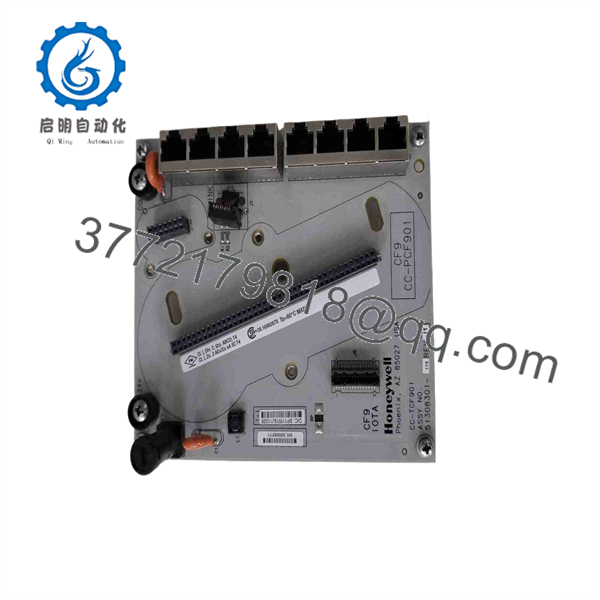
CC-TCF901
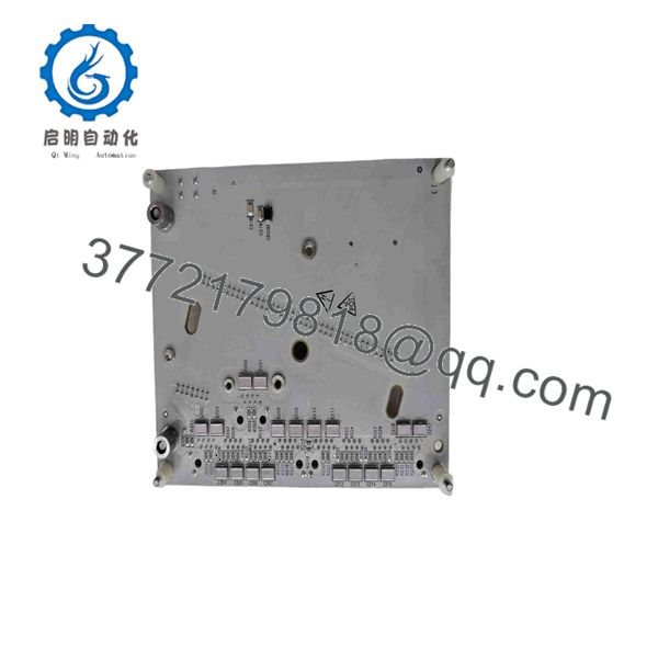
CC-TCF901
Frequently Asked Questions (FAQ)
Q1: What is the Honeywell CC-TCF901?
CC- is the CF9 Control Firewall Input/Output Termination Assembly used with the Honeywell CC- Control Firewall in Series C architectures.
Q2: How many network ports does CC- have?
The CF9 IOTA provides nine RJ-45 FTE ports. Eight are used for in-cabinet FTE connections, while the ninth provides the supervisory FTE uplink.
Q3: Is CC- the Control Firewall itself?
No. CC- is the IOTA/termination assembly. The associated Control Firewall module is , which mounts onto the IOTA.
Q4: Can CC- be used without CC-?
CC- is designed as the physical interface and mounting assembly for the CC- Control Firewall. Verify the complete cabinet architecture before treating the IOTA as a standalone network component.
Q5: Can FTE A and FTE B cables be connected interchangeably?
No. Honeywell’s Control Firewall documentation explicitly warns against mixing FTE A and FTE B link cables on the same IOTA. Preserve the documented network assignment during replacement.
Q6: Does CC- support fiber connections?
The CF9 architecture supports optional Honeywell fiber modules, including the documented CC-FSMX01 single-mode and CC-FMMX01 multi-mode modules. Confirm the exact installed fiber module and connector before replacement.
Q7: What should be verified before purchasing a replacement CC-?
Verify the complete CC- model, associated CC- firewall module, cabinet/carrier arrangement, nine-port FTE topology, FTE A/B assignments, fiber configuration if applicable, board revision, and supplier-specific condition. Some commercial listings associate CC- with order number 51308301-175, but the exact nameplate/order number should be confirmed against the installed hardware before procurement.



