
 WhatsApp: +86 16626708626
 Email:
  Phone: +86 16626708626
Description
Key Technical Specifications
| Parameter | Value |
|---|---|
| Model | CC-TDOB01 |
| Manufacturer | Honeywell |
| System | Experion PKS Series C |
| Product Type | Bussed 24 VDC Digital Output IOTA |
| Compatible I/O Module | CC-PDOB01 |
| Output Channels | 32 |
| Output Type | Source |
| IOTA Configuration | Non-redundant |
| IOTA Size | 9 inches |
| Load Voltage | 15–30 VDC |
| Maximum Current per Channel | 0.5 A |
| Galvanic Isolation | 1,500 VAC RMS or ±1,500 VDC |
Honeywell’s Series C specification explicitly pairs CC-PDOB01 with CC-TDOB01 for the non-redundant configuration and CC-TDOB11 for redundant operation. The same specification identifies the output as source-type, with 32 channels and a 0.5 A maximum per channel.
Product Introduction
The Honeywell CC-TDOB01 is a 9-inch non-redundant IOTA for the Series C CC-PDOB01 32-channel bussed 24 VDC digital output module. It provides the field termination and power interface for source-type discrete outputs used with devices such as solenoids, relays, and indicator circuits. The CC-PDOB01 architecture includes electronic short-circuit protection and supports internal or externally supplied field power.
Installation & Configuration Guide
Stage 1 — Pre-Installation
- Confirm that the installed I/O module is CC-PDOB01.
- Verify that the cabinet requires a 9-inch non-redundant digital-output IOTA.
- Confirm that the application uses bussed 24 VDC source outputs.
- Record all 32 output-channel assignments, field-device tags, terminal numbers, and power-source arrangements.
- Determine whether the field power is supplied internally by the Honeywell system or through an approved external 24 VDC source.
- Back up the relevant Experion PKS configuration.
- Photograph the existing terminal arrangement and power connections before removal.
- Check the replacement IOTA for damaged terminals, corrosion, contamination, or evidence of rework.
- ⚠️ Safety: Place affected output loops in the approved maintenance state before disconnecting field wiring.
- Apply appropriate ESD controls when handling the IOTA and CC-PDOB01.
Typical preparation time: 15–30 minutes for a documented cabinet.
Stage 2 — Removing Old Module
- Isolate the applicable system and field power according to the site maintenance procedure.
- Verify that external 24 VDC power is de-energized and correctly isolated.
- Record the internal/external power selection and wiring before disconnecting conductors.
- Label every field conductor by output channel.
- Photograph TB1, TB2, TB3, and power connections where applicable.
- Disconnect field wiring without disturbing neighboring I/O circuits.
- Remove the CC- module according to the Series C installation procedure.
- Release the IOTA mounting hardware.
- Remove the CC-TDOB01 and place it in ESD-safe packaging.
- Inspect the cabinet connector and field terminals before installing the replacement.
⚠️ Critical: Honeywell documentation warns that reversed external 24 VDC power can damage the I/O module. Verify polarity before energization.
Stage 3 — Installing New Module
- Inspect the replacement CC-TDOB01 before installation.
- Verify the exact CC-TDOB01 model marking.
- Mount the 9-inch IOTA in the designated Series C cabinet position.
- Secure the assembly according to the applicable Honeywell installation procedure.
- Install the compatible output module.
- Reconnect the field conductors channel by channel against the wiring record.
- Verify common-return and bussed-output wiring.
- Confirm the field power source and polarity.
- Verify that the expected 15–30 VDC load range is appropriate for the connected field devices.
- Recheck every output termination before restoring power.
- Do not substitute CC-TDOD01 or CC-TDOR01 based only on physical fit; the output topology and electrical characteristics differ.
- If a redundant architecture is required, verify the cabinet and IOTA configuration before selecting CC-TDOB11 instead.
Honeywell identifies CC- as the non-redundant 9-inch IOTA for CC- and CC-TDOB11 as its redundant 12-inch counterpart.
Typical replacement time: 30–60 minutes, depending on field-wiring density.
Stage 4 — Power-On & Testing
- Perform a final inspection of all output and power connections.
- Confirm external 24 VDC polarity before energizing the I/O.
- Restore power using the approved startup sequence.
- Verify that CC- initializes without I/O diagnostics.
- Check the configured output channels in Experion PKS.
- Test representative outputs individually using an approved maintenance procedure.
- Verify the expected field voltage at the load terminals.
- Confirm that connected solenoids, relays, or indicators respond correctly.
- Check for output-circuit, field-wiring, or short-circuit diagnostic messages.
- If a short-circuit protection event occurs, locate and clear the field fault before attempting to restore the channel.
- Confirm that the affected output returns to the intended control mode.
- Compare all tested output states with the pre-maintenance record.
- Return the equipment to normal service only after operator and control-engineering approval.
- Record the replacement model, revision, traceability information, test results, and removed-part disposition.
The Series C 24 VDC digital-output architecture detects excessive output current and removes power from the affected channel. Honeywell documentation also describes Soft Failure 23 and Soft Failure 180 for the applicable short-circuit condition.
⚠️ Field warning: Do not treat a short-circuit-protected output as permission to leave a field fault connected. The protection circuit removes power from the affected channel; the wiring fault still needs to be identified and corrected before normal operation is restored.
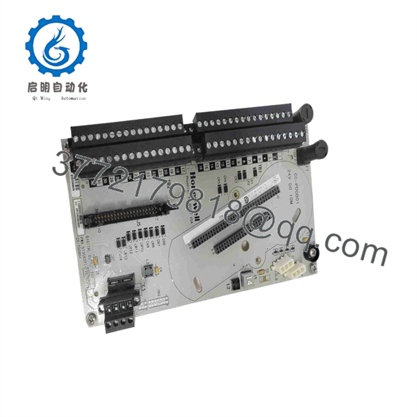
CC-TDOB01
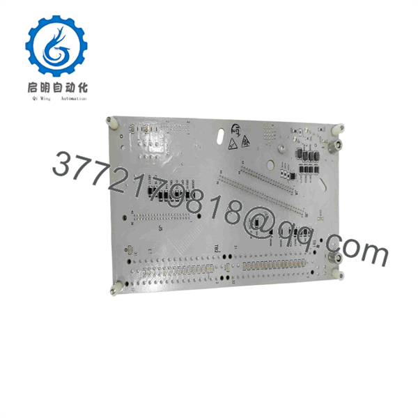
CC-TDOB01
Frequently Asked Questions (FAQ)
Q1: What is the Honeywell CC-?
CC- is a 9-inch non-redundant I/O termination assembly for the Honeywell Series C CC- 32-channel bussed 24 VDC digital output module.
Q2: How many outputs does the CC- support?
The associated CC- provides 32 digital output channels. The outputs are source-type and use a bussed 24 VDC architecture.
Q3: What is the maximum output current?
Honeywell specifies 0.5 A maximum per channel. It also specifies group and module current limits that depend on the number of simultaneous short-circuit conditions.
Q4: Is CC- redundant?
No. CC- is the 9-inch non-redundant IOTA. CC-TDOB11 is the corresponding 12-inch redundant IOTA for CC-.
Q5: Does CC- provide short-circuit protection?
Yes. The CC-/CC- architecture uses electronic short-circuit protection. When an excessive-current condition is detected, the affected output is de-energized until the field fault is corrected.
Q6: Can external 24 VDC field power be used?
Yes. Honeywell documentation describes both internal and external field-power arrangements for the bussed 24 VDC digital output architecture. When external power is used, polarity must be verified carefully before energization.
Q7: Is CC- the same as CC-?
No. CC- is the electronic digital output module; CC- is the associated 9-inch non-redundant IOTA. Both are required as part of the applicable Series C hardware configuration.



