
 WhatsApp: +86 16626708626
 Email:
  Phone: +86 16626708626
Description
Key Technical Specifications
| Parameter | Value |
|---|---|
| Product Model | FC-DCOM-232485 |
| Documented FTA Designation | DCOM-232/485 / FS-DCOM-232/485 |
| Manufacturer | Honeywell |
| Product Family | Safety Manager |
| Product Type | Communication Interface Field Termination Assembly |
| RS-232 Ports | 1 |
| RS-485/422 Ports | 2 |
| RS-232 Electrical Standard | EIA/TIA-232 |
| RS-232 Data Rate | 0 to 250 kBaud |
| RS-485/422 Electrical Standard | EIA/TIA-485-A |
| RS-485/422 Data Rate | 0 to 2 MBaud |
| Transmission Modes | Transparent, FM0, FM1, Manchester |
| Input Voltage | 5 VDC ±5% |
| Maximum Input Current | 500 mA |
| Power Source | Connected Control Processor(s) |
| Separate Field Power Wiring | Not required |
| Mounting | DIN EN rail |
| Supported Rail | TS32 or TS35 × 7.5 |
| Required Rail Length | Approximately 117 mm |
| Earth Connection | Required |
| Operating Temperature | Verify installed hardware revision and cabinet specification |
| Certifications | CE, TÜV, UL, FM |
Honeywell’s Safety Manager hardware documentation identifies the DCOM-232/485 as the combined RS-232/RS-485 communication interface FTA. It can be driven by one or a redundant pair of Control Processors and receives its supply through the connected processor(s), rather than requiring a separate field power connection.
The documented hardware is labeled FS-DCOM-232/485 V2.1, while supplier catalogs commonly identify the procurement part as FC-DCOM-232/485. Confirm both the catalog number and physical label when purchasing a replacement.
Product Introduction
The Honeywell FC-DCOM-232485 is a Safety Manager communication interface FTA that provides serial connectivity between Honeywell Control Processors and external equipment. It provides one RS-232 interface and two RS-485/RS-422 interfaces, with documented data rates up to 250 kBaud and 2 MBaud respectively.
This is a physical communication interface, not a general-purpose DCS I/O module. Correct cable type, interface selection, baud rate, differential polarity, grounding, and Safety Manager configuration must all match the existing installation before commissioning.
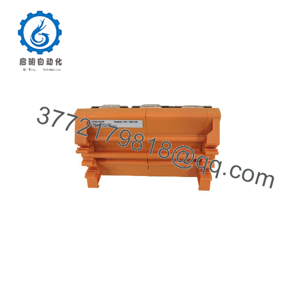
FC-DCOM-232485
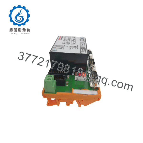
FC-DCOM-232485
Installation & Configuration Guide
Stage 1: Pre-Installation Preparation — Approx. 10 Minutes
⚠️ Safety First
- Notify operations before taking the Safety Manager communication link out of service.
- Confirm the affected external equipment is in a safe state.
- Follow the site’s Safety Manager maintenance procedure.
- Apply lockout/tagout where cabinet access requires power isolation.
- Do not disconnect a live safety communication interface unless the approved maintenance procedure explicitly permits it.
Tools Required
- ESD wrist strap
- PH1 screwdriver
- Digital multimeter
- Wire labels
- Smartphone for photographs
- Laptop or approved Honeywell engineering workstation
- Appropriate serial test equipment, if permitted by the site procedure
Data Backup
Before removing the existing unit:
- Record the exact part number and hardware revision.
- Photograph the complete wiring arrangement.
- Document which connector is being used:
- RS-232
- RS-485
- RS-422
- Record communication parameters:
- Baud rate
- Data format
- Transmission mode
- Node configuration
- Cable polarity
- Photograph the earth connection and cable shield arrangement.
Honeywell documentation specifically requires the DCOM-232/485 to be connected to earth; this connection also bonds the shields of the internal cables and field connector housings to cabinet earth.
Stage 2: Removing the Old Module — Approx. 10 Minutes
Steps
- Confirm the correct FC-DCOM-232485 location.
- Verify the communication link is approved for maintenance.
- Label every communication cable before removal.
- Photograph connector orientation and wiring.
- Disconnect the Control Processor connection.
- Disconnect the external RS-232/RS-485/RS-422 connections.
- Disconnect the earth connection only after the communication wiring has been secured.
- Release the DIN-rail retaining mechanism.
- Remove the FTA without pulling on the communication cables.
⚠️ Critical:
Do not rely on cable color alone. RS-485/RS-422 polarity and termination arrangements must be documented before removal.
Keep the original FTA until the replacement has completed communication testing.
Stage 3: Installing the New Module — Approx. 10 Minutes
- Wear an ESD wrist strap.
- Verify the replacement identification:
- FC-DCOM-232485
- FC-/485
- FS-/485
- Configuration Clone — Critical:
- Match the original interface.
- Match baud rate.
- Match transmission mode.
- Match RS-485/RS-422 polarity.
- Reproduce the original cable arrangement.
- Reconnect the earth conductor exactly as documented.
- Mount the unit on the appropriate TS32 or TS35 × 7.5 DIN rail.
- Connect the Control Processor cable.
- Reconnect the external communication cables.
- Verify all connectors are mechanically secured.
Self-Checklist
- Exact model/revision verified
- DIN-rail mounting secure
- Control Processor connection secure
- RS-232/RS-485/RS-422 wiring matched
- Differential polarity verified
- Earth connection restored
- Cable shields correctly terminated
Stage 4: Power-On & Testing — Approx. 15–20 Minutes
Pre-Power Check
- Confirm the Control Processor supply is within the documented 5 VDC ±5% range.
- Verify the communication wiring.
- Check the earth connection.
- Confirm there are no shorts between communication conductors and earth.
The /485 is supplied by the connected Control Processor(s), with a maximum documented input current of 500 mA.
Power-On Steps
- Restore the approved system power.
- Observe the module status indications.
- Verify Control Processor communication.
- Confirm the configured serial interface.
- Test the RS-232 connection if used.
- Test RS-485/RS-422 communication if used.
- Verify the connected external device responds correctly.
- Return the communication link to normal service only after the safety-system procedure is satisfied.
⚠️ Troubleshooting Note
- No communication: Check interface selection, baud rate, cable pinout, and grounding.
- RS-485 communication unstable: Check differential polarity, cable shielding, and bus termination.
- RS-232 works but RS-485 does not: Treat these as separate physical interfaces; verify the RS-485 wiring rather than changing software parameters blindly.
- Module does not initialize: Verify the 5 VDC supply from the Control Processor and inspect the CP connection.
Frequently Asked Questions (FAQ)
Q1: What is the Honeywell FC-DCOM-232485 used for?
It provides serial communication interfaces for the Honeywell Safety Manager architecture. The documented /485 FTA provides one RS-232 interface and two RS-485/RS-422 interfaces.
It is therefore a communication interface FTA, not a conventional analog or discrete I/O module.
Q2: Are FC-DCOM-232485 and FS-/485 the same product?
They are closely associated identifiers, but procurement should not rely on the names alone.
Honeywell documentation identifies the physical FTA as , while commercial catalogs use as the part number. The hardware reference identifies the unit as FS-/485 V2.1.
Before ordering, compare the complete label, revision, connector arrangement, and existing system documentation.
Q3: Does the FC- require a separate 24 VDC power supply?
No. The documented /485 FTA receives its supply from the connected Control Processor or redundant Control Processors. The specified input is 5 VDC ±5%, with a maximum current of 500 mA.
Do not connect a separate 24 VDC supply simply because the module is installed in a conventional industrial control cabinet.
Q4: What communication speeds does it support?
The documented limits are:
- RS-232: 0 to 250 kBaud
- RS-485/RS-422: 0 to 2 MBaud
The RS-485/RS-422 interface also supports transparent, FM0, FM1, and Manchester transmission modes.
The connected device and Safety Manager configuration determine the actual operating settings.
Q5: Can I replace FC- with a generic RS-485 converter?
Not as a direct hardware replacement.
A generic RS-485 converter may provide the electrical interface, but it does not reproduce the Honeywell Safety Manager FTA architecture, Control Processor connection, grounding arrangement, or documented transmission modes.
For a live Safety Manager installation, treat the FC- as a system-specific interface rather than a generic serial converter.
Q6: Can this module be hot-swapped?
Do not assume it can.
The /485 can be driven by a single Control Processor or redundant Control Processors, but whether a particular installation permits online replacement depends on the Safety Manager architecture and the approved site maintenance procedure.
For safety-system hardware, follow the installed system’s maintenance procedure rather than applying a generic PLC hot-swap rule.
Q7: What condition should I specify when buying a replacement?
Specify the condition explicitly:
- New Original / New Surplus: Unused original Honeywell inventory.
- Factory Sealed: Original unopened packaging, if available.
- Refurbished (tested): Previously used hardware that has undergone documented inspection and functional testing.
For this particular interface, also request photographs of the model label, revision, connectors, and terminal arrangement before purchase.
Q8: What inspection process should be completed before installing surplus FC-?
Inbound Inspection & Traceability
- Verify Honeywell identification.
- Confirm FC- / FC-/485 designation.
- Check the physical hardware revision.
- Inspect the DIN-rail housing.
- Check connectors for bent contacts or damage.
- Look for corrosion, repair marks, or contamination.
Live Functional Testing
Use a genuine Honeywell Safety Manager test environment where available.
Verify:
- Power-up behavior.
- Control Processor communication.
- RS-232 communication.
- RS-485/RS-422 communication.
- Applicable transmission modes.
- Communication stability under continuous operation.
Electrical Parameter Testing
- Verify 5 VDC supply compatibility.
- Check current consumption.
- Check earth continuity.
- Inspect communication-line electrical characteristics.
Configuration Verification
Document:
- Hardware revision.
- Interface being used.
- Baud rate.
- Transmission mode.
- RS-485/RS-422 polarity.
- Cable and shield arrangement.
- DIN-rail installation position.
Final QC & Packaging
- QC inspector sign-off.
- ESD-safe packaging.
- Connector protection.
- Bubble-wrap protection.
- Heavy-duty corrugated packaging.
- QC Passed label with inspection date.
Test photos and the functional test report should be available upon request.



