
 WhatsApp: +86 16626708626
 Email:
  Phone: +86 16626708626
Description
Key Technical Specifications
| Parameter | Value |
|---|---|
| Manufacturer | Honeywell |
| Model | FC-RUSIO-3224 |
| Product Type | Remote Universal Safe I/O Module |
| System | Honeywell Safety Manager / Safety Manager SC |
| Number of Channels | 32 |
| Supply Voltage | 24 VDC, -15% to +30% |
| Maximum Module Current | 300 mA, excluding field load |
| Channel Configuration | Universal, software-configurable |
| Digital Input | Supported |
| Digital Output | Supported |
| Analog Input | 0–20 mA / 4–20 mA |
| Analog Output | 0–20 mA / 4–20 mA |
| Digital Output Rating | 0.5 A current-limited per channel |
| Operating Temperature, Outside | -40 to +70 °C |
| Operating Temperature, Inside | -40 to +90 °C |
| Storage Temperature | -40 to +85 °C |
| Relative Humidity | 10–95%, non-condensing |
| Dimensions | 145 × 165.1 × 72.4 mm |
| Weight | Approximately 0.66–0.70 kg |
| Mounting | DIN rail or cabinet/sub-rail with IOTA termination assembly |
| Safety Application | Safety Manager safety I/O |
| Certification Status | TÜV certification documentation available |
The technical reference material identifies 32 channels, 24 VDC operation, 300 mA maximum module current without field load, and the -40 to +70 °C external operating range.
The FC-RUSIO-3224 supports individually configurable universal channels, including digital and analog I/O functions. One technical listing specifies 0.5 A current-limited digital outputs and 0–20 mA / 4–20 mA analog I/O.
Product Introduction
Honeywell FC-RUSIO-3224 is a 32-channel Remote Universal Safe I/O module for the Honeywell Safety Manager and Safety Manager SC platforms. Its channels can be configured for different field signal functions, reducing the need to stock separate safety I/O module types. Honeywell’s TÜV documentation identifies the FC-RUSIO-3224 as a 24 V, 32-channel Remote Universal Safe I/O module.
The module operates from a nominal 24 VDC supply and supports industrial temperature ranges suitable for cabinet and remote I/O installations. Before replacement, verify the IOTA termination assembly, channel configuration, firmware/software revision, and whether the application requires redundant I/O.
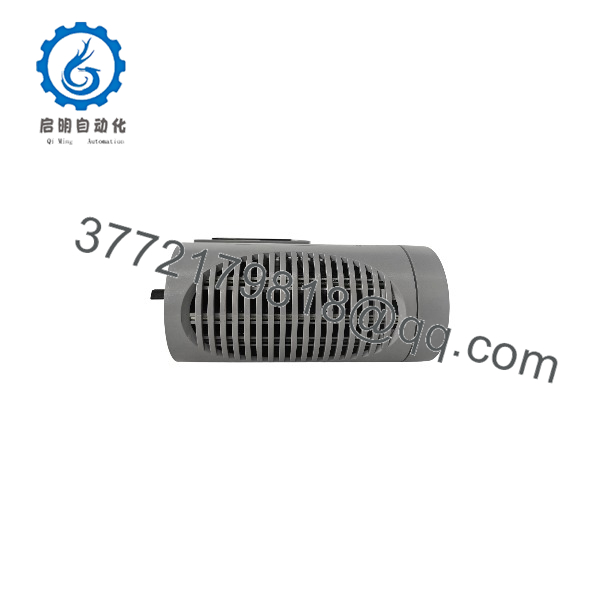
FC-RUSIO-3224
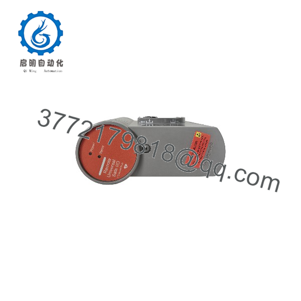
FC-RUSIO-3224
Installation & Configuration Guide
Stage 1: Pre-Installation Preparation
⚠️ Safety First:
FC-RUSIO-3224 is safety-system hardware. Do not treat it as an ordinary PLC I/O card. Put the affected Safety Manager function into the plant-approved maintenance state, follow the required bypass/inhibit procedure, and apply LOTO where required.
Tools Required:
- ESD wrist strap
- Appropriate screwdriver
- Digital multimeter
- Wire labels
- Smartphone or camera
- Safety Manager engineering workstation
- Current I/O configuration documentation
Data Backup:
- Record the complete FC-RUSIO-3224 identification and revision information.
- Photograph the existing module and IOTA termination assembly.
- Record all 32 channel assignments.
- Export or verify the current Safety Builder configuration.
- Record whether the installation uses one module on a non-redundant IOTA or two modules on a redundant IOTA.
A single FC- can be installed on a non-redundant IOTA, while redundant configurations use two FC- modules with an appropriate redundant I/O termination arrangement.
Stage 2: Removing the Old Module
- Place the relevant safety function into the approved maintenance state.
- Set the applicable IOTA power switch to OFF.
- Confirm the module is de-energized.
- Photograph the module position and IOTA connections.
- Loosen the module locking screw.
- Press the two module removal levers into the removal position.
- Pull the FC- straight away from the IOTA connectors.
- Inspect the connectors for contamination, bent contacts, or mechanical damage.
The documented removal procedure specifically calls for turning the applicable IOTA power switch OFF, loosening the locking screw, operating the side removal levers, and then removing the module from the IOTA.
Stage 3: Installing the New Module
- Confirm the replacement model and revision.
- Verify that the replacement is intended for the same Safety Manager configuration.
- Confirm the IOTA type before installation.
- Make sure the module removal levers are in their normal upright position.
- Hold the module correctly over the IOTA connectors.
- Push the module down firmly onto the connectors.
- Tighten the module locking screw.
- Verify that the module is mechanically secure.
Configuration Clone — Critical:
The 32 channels are configurable, so do not assume that a replacement module automatically has the correct channel configuration.
Verify:
- Digital input configuration
- Digital output configuration
- Analog input range
- Analog output range
- Line monitoring
- Channel assignments
- Alarm and diagnostic settings
- Safety logic references
The available technical documentation states that channel configuration is performed through Safety Builder.
Self-Checklist:
- FC- model verified
- Hardware revision documented
- Correct IOTA verified
- Module fully seated
- Locking screw secured
- Channel configuration backed up
- Redundancy arrangement verified
Stage 4: Power-On & Testing
Pre-Power Check:
- Verify the 24 VDC supply polarity.
- Check the supply voltage before connecting the module.
- Inspect field wiring for shorts.
- Confirm the field load is within the module/I/O configuration limits.
- Verify the correct IOTA power switch.
Power-On Steps:
- Set the applicable IOTA power switch to ON.
- Observe the module diagnostic indicators.
- Verify module communication with the Safety Manager system.
- Open the Safety Builder configuration.
- Confirm all configured channels are recognized.
- Test digital inputs using approved field simulation.
- Test digital outputs using an appropriate controlled load.
- Verify analog input/output values where configured.
- Check module and channel diagnostics.
- Complete the required safety-function validation before returning the process to normal service.
⚠️ Important:
Do not use a generic PLC I/O test as the sole acceptance test for a Safety Manager module. The final test must verify the actual safety function, including the configured logic, field signal path, diagnostics, and defined safe state.
Frequently Asked Questions (FAQ)
Q1: What is Honeywell FC-?
FC- is a Remote Universal Safe I/O module for Honeywell Safety Manager systems. Honeywell’s TÜV documentation specifies it as a 24 V, 32-channel module with conformal coating.
Q2: How many I/O channels does FC- have?
It has 32 universal channels. The channel functions can be configured according to the Safety Manager application rather than being permanently assigned to only one signal type.
Q3: What power supply does FC- require?
The nominal supply is 24 VDC, with a specified tolerance of -15% to +30%. Maximum module current is approximately 300 mA without field load.
Q4: Can FC- be used in a redundant configuration?
Yes. Technical documentation describes a redundant arrangement using two FC- modules on a redundant IOTA. A single module can be used with a non-redundant IOTA.
Q5: What temperature range does FC- support?
The documented outside-module operating range is -40 to +70 °C, while the inside-module specification extends to -40 to +90 °C. Storage is specified at -40 to +85 °C.
Q6: Can I simply swap FC- and restore power?
Physically replacing the module is only part of the job. The IOTA type, channel configuration, Safety Builder configuration, redundancy arrangement, and safety application must all be checked. The module should then undergo the site’s required safety-function verification before being returned to service.
Q7: What should I provide when purchasing a replacement FC-?
Provide the complete FC- part number, hardware revision, existing IOTA model, Safety Manager/Safety Manager SC release, and whether the installation is redundant. A photograph of the installed module label is particularly useful because the Honeywell Safety Manager platform has multiple hardware and software revisions. Honeywell’s certification documentation confirms FC- revision-controlled hardware.



